


CANON Digital Galvano Scanner System GM-1000 Series
Users Manual 1.20
104
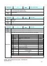
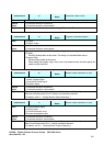
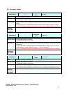
Command ID 26
Command
Name
Parameter Value Check
Data Parameter ID
Return
Value
0: Command execution successful
1: Command execution unsuccessful
Explanation This command returns the parameter setting of Parameter ID.
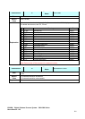
Command ID 30
Command
Name
Program Coordinate System
Data 0: Z phase
1: Program Origin
Return
Value
0: Command execution successful
1: Command execution unsuccessful
Explanation For a raster scan, the center of the oscillation angle can be changed.
0: Z phase
Set the Z-phase position as the center. This setting is in the default after start up.
1: Program Origin
Set the current position as the center.
When setting the program origin, move once to the desired center and then specify the
position by this command.
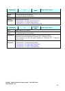
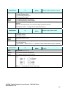
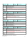
Command ID 40
Command
Name
Monitor Output Selection A2 (A8)
Data 0: Head1 A phase signal
1: Head2 A phase signal
2: Corrected A phase signal
3: Deviation signal
Return
Value
0: Command execution successful
1: Command execution unsuccessful
Explanation The output signal of analog monitor output A2 (Axis 1) and A8 (Axis 2) can be selected.
When the controller starts, the 3: Position error has been selected.
(For details, see5.2. , “Analog Monitor Output Selecting ”)
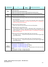
Command ID 41
Command
Name
Monitor Output Selection A3 (A9)
Data 0: Current position signal
1: Velocity signal
2: Corrected encoder count
3: Encoder interpolation data
Return
Value
0: Command execution successful
1: Command execution unsuccessful
Explanation The output signal of analog monitor output A3 (Axis 1) and A9 (Axis 2) can be selected.
When the controller starts, the 1: Velocity has been selected.
(For details, see 5.2. , “Analog Monitor Output Selecting ”)