


CANON Digital Galvano Scanner System GM-1000 Series
Users Manual 1.20
26
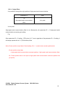
2.8.3. High-speed serial communication
To control the mirror to an arbitrary position by marking or any other application, target position data
updated as required can be given to the controller by using high-speed serial communication.
By setting, the controller can be started up in the mode of tracking a target position specified by
high-speed serial communication. (For details, see 6.1. “Setting Controller Start Up Mode”)
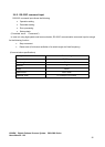
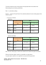
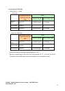
(Communication specifications)
Base clock (CLK) 2 MHz
Frame sync (FS) 100 kHz
Data (DAT) 20 bits (Position data: 16 bits)
Status (STS) 20 bits
Transmission system Differential signal
Signal level
5V-TTL, LVDS
(Selectable by the optional IF board)
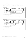
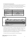
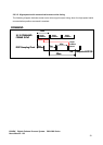
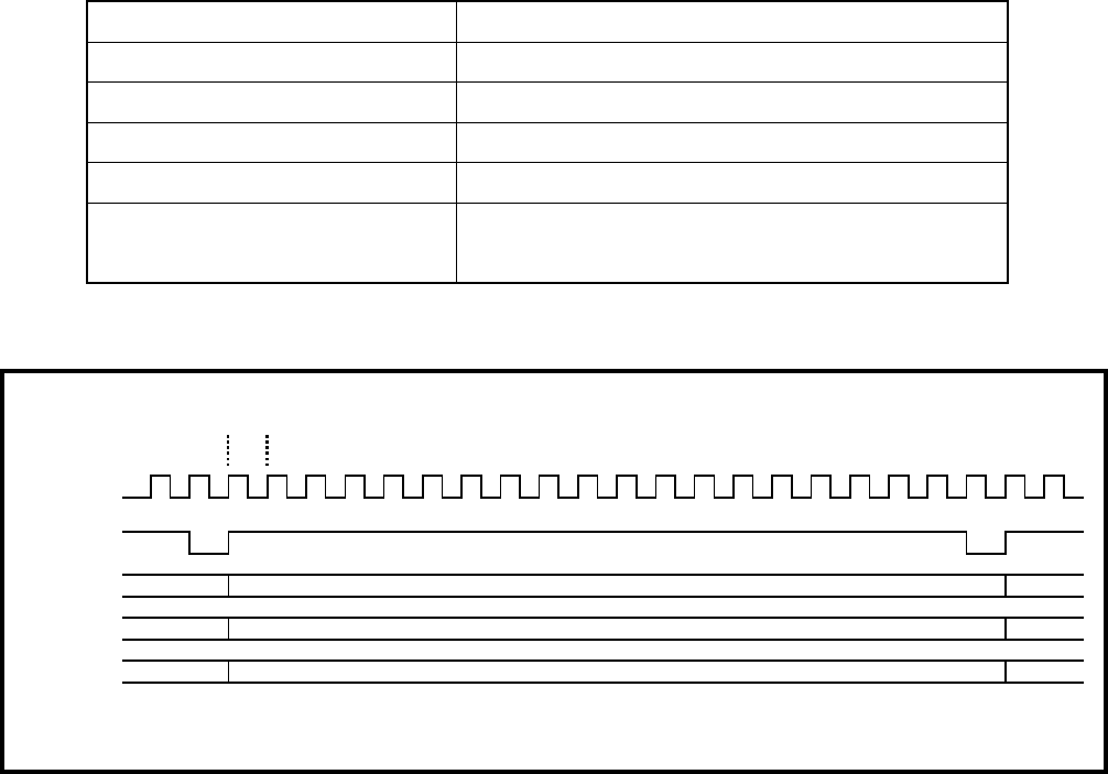
(Timing Diagram)
As indicated in the above timing diagram, it is necessary to always continuously input the CLK, FS,
and DAT signals to the GC-201. In the event that the signal is disconnected, or the signal’s timing is
incorrect, the GC-201 will output an error signal (Clock Lack). (For details, See 10.2. “Errors”.)
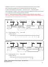
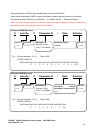
When switching to high-speed serial communication mode, or starting up in high-speed serial
communication mode when turning on the controller’s power supply, input of the high-speed serial
communication signal (all of CLK, FS, and DAT) beforehand is necessary.
For the support of other communication specifications, contact the Sales Department.
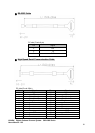
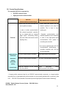
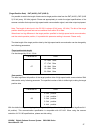
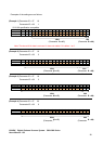
Timing Diagram
1234567891011121314151617181920
CLK
FS
DAT (AXIS 1)
AXIS 1 DATA -1 AXIS 1 DATA
A
XIS 1 DATA +
1
DAT (AXIS 2)
AXIS 2 DATA -1 AXIS 2 DATA
A
XIS 2 DATA +
1
STS
Status -1 Status Status +1
Input Signal to GC-201 : CLK , FS , DAT
Ounput Signal from GC-201 : STS
2MHz