


CANON Digital Galvano Scanner System GM-1000 Series
Users Manual 1.20
72
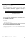
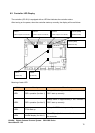
6.2. Controller LED Display
The controller (GC-201) is equipped with an LED that indicates the controller status.
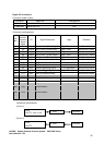
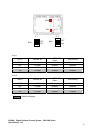
After turning on the power, when the controller starts up normally, the display will be as follows.
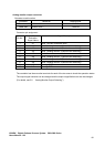
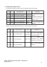
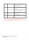
Meaning of each LED
LED No. Meaning Remarks
LED1 DSP1 operation (for Axis 1)
Always blinks in approximately 2 sec. intervals if
DSP1 start up correctly.
LED2 DSP1 operation (for Axis 2)
Always blinks in approximately 2 sec. intervals if
DSP1 start up correctly.
LED3 FPGA Start up
Always lit if FPGA start up correctly.
LED4 ALARM display (for Axis 1)
This LED (red) is lit when a malfunction occurs with
the controller.
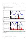
LED1
(Blinks in approx 2 sec. intervals)
LED2
(Blinks in approx 2 sec.intervals)
LED4 (Red)
(Not turns on)
LED3
(Blinks in approx 1 sec. intervals)
LED5 (Red)
(Not turns on)
LED7
(Turns on)
LED6
(Turns on)