


CANON Digital Galvano Scanner System GM-1000 Series
Users Manual 1.20
69
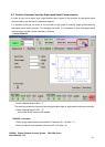
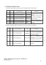
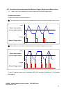
5.3. Digital Input-Output Function
The controller has a digital input-output function for checking the status of the controller.
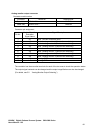
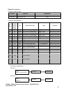
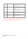
Pin
No.
I/O Signal Description Logic Explanation
A1
Output Axis 1 Error 1 (Priority high) High: Error If an error occurs, the
corresponding error signal is
output.
According to the priority of the
error, Error 1 or 2 is output.
See 9-2, “Errors.”
B1
Output Axis 1 Error 2 (Priority low) High: Error
B2
Output Axis 2 Error 1 (Priority high) High: Error
A3
Output Axis 2 Error 2 (Priority low) High: Error
A2
Output Axis 1 servo interrupt period Edge Output is timed according to
an internal controller servo
interrupt..
B3
Output Axis 2 servo interrupt period Edge
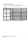
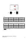
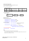
In addition, the following digital I/O is prepared as an operation setting of the controller.
Pin
No.
I/O Signal Description Logic Explanation
A5 Input External Sampling Signal
↑: INT
generation
Input when an external signal is
used for servo sampling clock.
(Do not use it usually.)
B5 Input External Trigger Signal High: FG_ON
See 6-2, “Operation that
synchronizes with external
trigger signal input (raster scan)
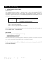
A6 Input Start up mode switching
See 6-1, “Setting Controller Start
Up Mode”