


2-3
Cisco AC/DC Power System User Guide, R1.0
May 2006
Chapter 2 System Installation
2.2 Install AC/DC Power System Components
2.2 Install AC/DC Power System Components
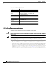
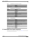
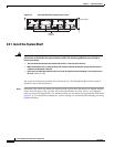
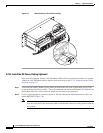
The following sections contain instructions for installing components. Figure 2-2 shows a drawing of the
Cisco AC/DC Power System without rectifiers.
Quick Installation Guide 1 Installation instructions
System documentation 1 Installation, provisioning, and troubleshooting
Table 2-2 Supplied Materials for the 1 RU Distribution Shelf
Description Qty Use
M6 0x20mm screw (thread forming) 4 Shelf mounting screws (ETSI racks/cabinets)
12-24 x 1/2” screw (thread forming) 4 Shelf mounting screws (ANSI, IEC racks/
cabinets)
M6 cage nut 4 Shelf mounting nut (ETSI racks/cabinets)
Mounting bracket 600mm ETSI rack 2 Ear mounts (ETSI racks/cabinets)
Quick disconnect circuit breakers 2 1RU Distribution Shelf
Cable ties 4 Securing cables
ESD wrist strap 1 ESD protection
Quick Installation Guide 1 Installation instructions
Table 2-3 Non-Supplied Materials
Description Qty Use
6AWG (16mm²) grounding cable 1 system shelf grounding
6AWG (16mm²) grounding cable 1 1RU Distribution grounding (if applicable)
10 to 8 AWG (6 to 10mm²) cables <8 DC load breaker connections (-48V and return)
22 AWG (0.34mm²) cables n/a 2A GMT fuse cabling
18 AWG (0.75mm²) cables n/a 5A GMT fuse cabling
14 AWG (2.5mm²) cables n/a 10/15A GMT fuse cabling
26 to 22AWG (0.14mm²- 0.34mm²)
cables
4 Alarm cabling
UL Listed double-hole lug 1/4in and
5/8in. center-to-center (lug part #
Panduit LCD6 -14A-L or equivalent)
2 Ground cable installation
Table 2-1 Supplied Materials for the System Shelf (continued)
Description Qty Use