


2-27
Cisco AC/DC Power System User Guide, R1.0
May 2006
Chapter 2 System Installation
2.5.2 Install 1 RU Distribution Shelf Load Connections
Step 1 Select the wire gauge for the application. See Table 2-7 on page 2-24 for wiring information.
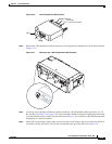
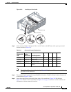
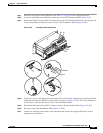
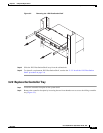
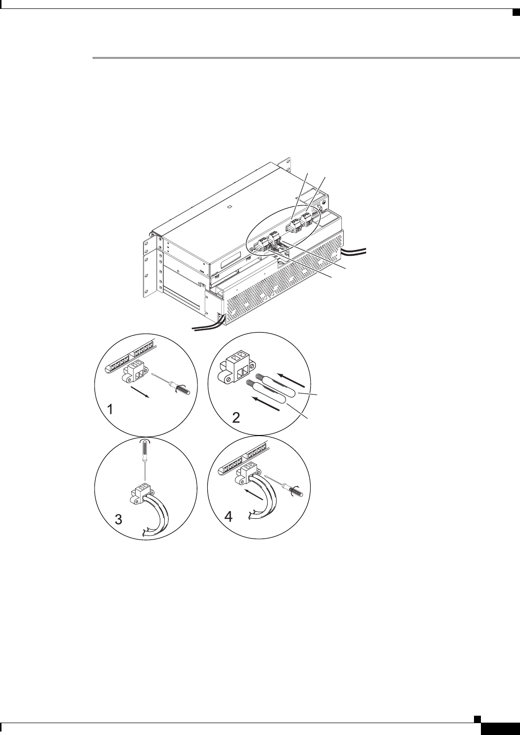
Step 2 Locate the load-and-return connections at the rear of the 1 RU Distribution Shelf (Figure 2-25).
Step 3 Remove the Phoenix Contact PC6™ connectors from the 1 RU Distribution Shelf by loosening the flat
screws and pulling the connectors away from the 1 RU Distribution Shelf (Figure 2-25 #1).
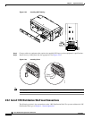
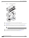
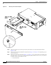
Figure 2-25 Installing Load Connections
Step 4
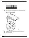
Connect the wires to the appropriate terminal for the load-and-return connections by inserting and then
tightening the connector (Phoenix Contact PC6™ connectors) (Figure 2-25 #2, #3). Allow enough of a
service loop to allow for the removal of the 1 RU Distribution Shelf.
Step 5 Reinstall the Phoenix Contact PC6™ connector to the 1 RU Distribution Shelf (Figure 2-25 #3).
Step 6 Reconnect to the 1RU Distribution Shelf (Figure 2-25 #4).
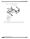
Step 7 Connect the load-and-return cables to the equipment that requires the supplied DC Power per that
equipment’s specifications.
Return
Load
A1
B1
B2
A2
124782