


3-5
Cisco AC/DC Power System User Guide, R1.0
May 2006
Chapter 3 Component Replacement
3.2.2 Replace the Controller Tray
• –J15 terminal block
• –J14/J13 terminal blocks
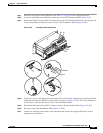
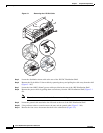
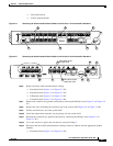
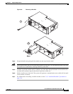
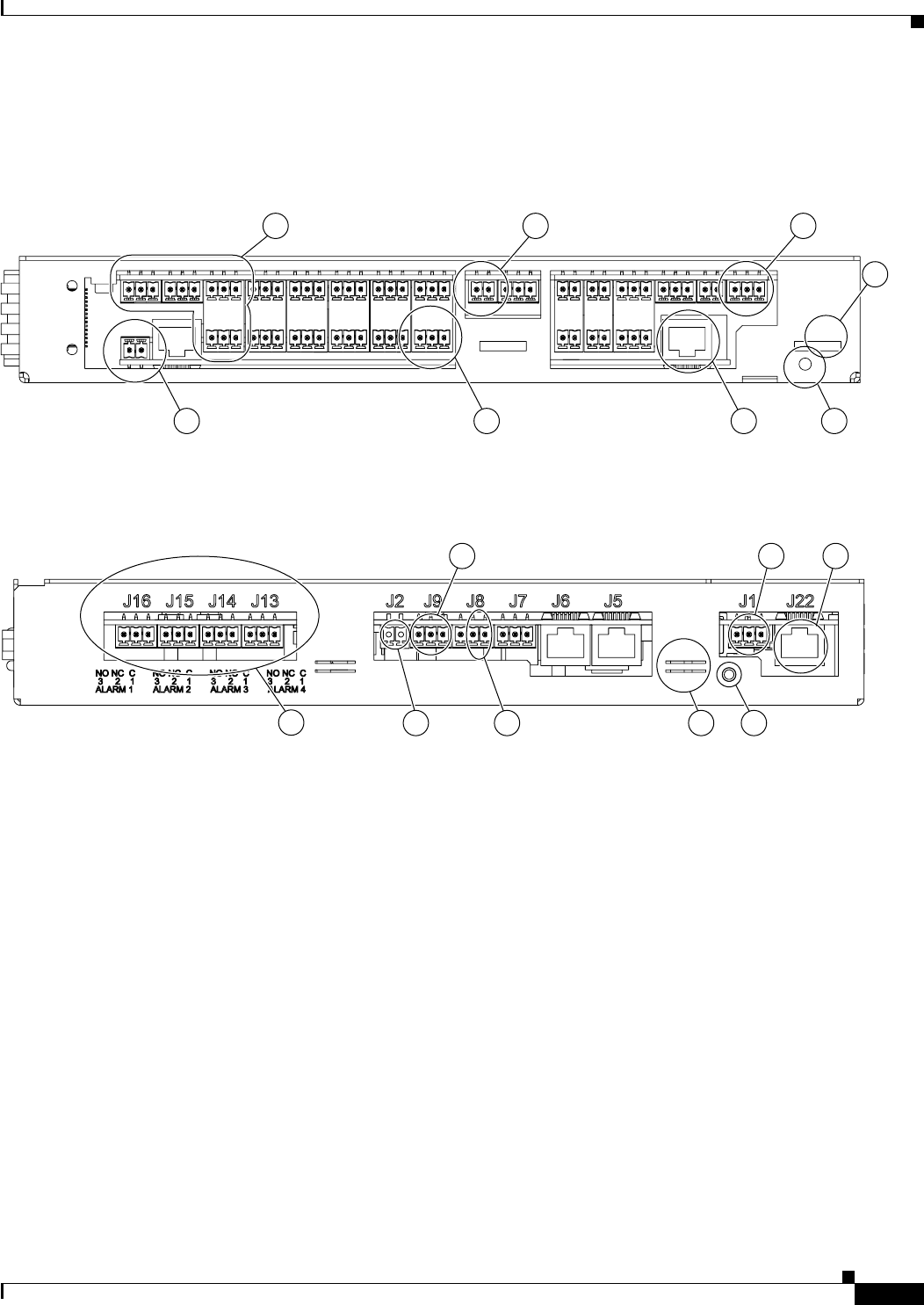
Figure 3-4 Removing the Alarm Interface Board Cable on the Version 1 of the Controller Hardware
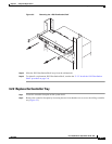
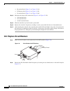
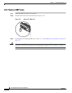
Figure 3-5 Removing the Alarm Interface Board Cable on the Version 2 of the Controller Hardware
Step 6
Remove the intra-shelf communications cabling:
• J9 terminal block (Figure 3-4 or Figure 3-5 #3)
• J8 terminal block (Figure 3-4 or Figure 3-5 #4)
• J1 Ethernet cable (Figure 3-4 or Figure 3-5 #5)
• J1 terminal block (Figure 3-4 or Figure 3-5 #6)
Step 7 Remove the controller tray ground connection by removing the Phillips screw (Figure 3-4 or Figure 3-5
#7).
Step 8 Remove the wire tie holding the controller tray in the system shelf (Figure 3-4 or Figure 3-5 #8).
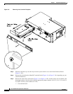
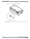
Step 9 Pull the controller tray out of the system shelf.
Step 10 Install the replacement controller tray by placing it in the system shelf.
Step 11 Reinstall the controller tray ground connection by connecting the Phillips screw (Figure 3-4 or
Figure 3-5 #7).
Step 12 Use a new wire tie to replace the one that was removed in Step 8.
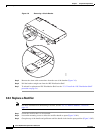
Step 13 Reconnect the intra-shelf communications cabling (cables are labeled with the appropriate jumper
number):
• J9 terminal block (Figure 3-4 or Figure 3-5 #3)
2
3
5
7
J1
J2
J3
J4
J5
3
4
J6
3
4
J1
J7
J8
J9
4
5
6
1
2
3
J10
J11
J12J13
J14
J15J16
J2
1
2
6
4
5
4
5
66
4
5
6
5
4
5
6
4
3
2
11
2
33
2
13
2
1
2
31 1
2
33
2
1
6
5
4
1
2
3
2
1
2
31
2
1
2
13
2
1
2
13
2
1
46
8
159329
1 3 5 7
6
8
42
124768
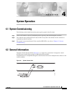
Wire to be on the
far right of J9
Wire to be on the
center pin of J8
41
2
8 7
563