


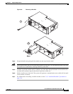
3-4
Cisco AC/DC Power System User Guide, R1.0
May 2006
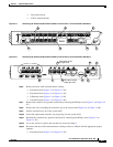
Chapter 3 Component Replacement
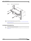
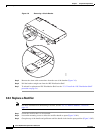
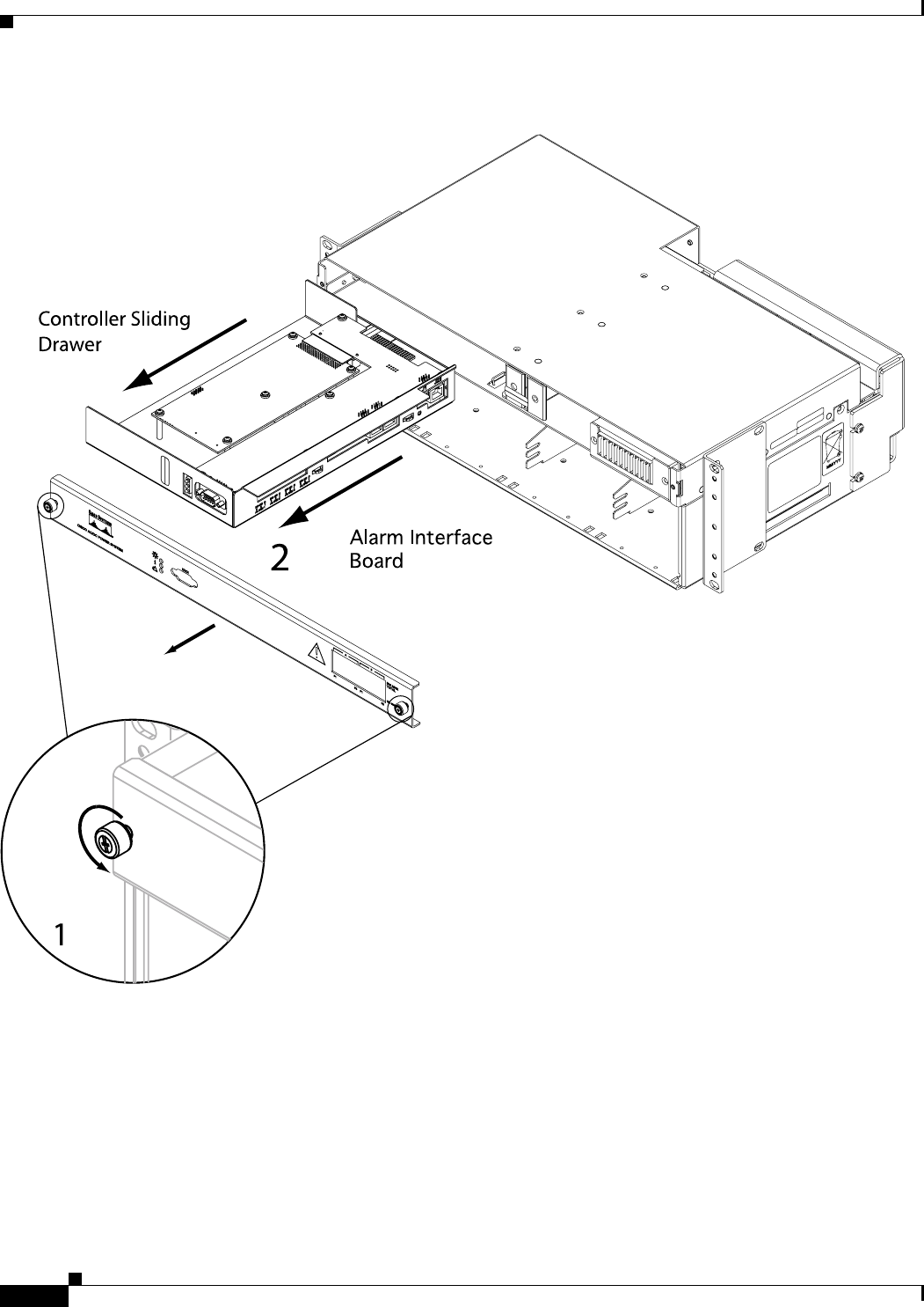
3.2.2 Replace the Controller Tray
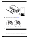
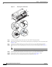
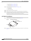
Figure 3-3 Removing the Controller Faceplate
Step 3
Slide the controller tray out and away from the system shelf to access the Alarm Interface Board
(Figure 3-3 #2).
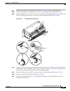
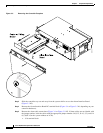
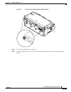
Step 4 Remove the Alarm Interface Board DC terminal block (Figure 3-4 or Figure 3-5 #1, depending on your
controller hardware).
Step 5 Remove the alarm cable connections (Figure 3-4 or Figure 3-5 #2). If alarm cables are not labeled with
the jumper number, label the cables with the appropriate jumper number: J16, J15, J14 (1,2,3), and J14
(4,5,6)/J13 (for the system without an LCD).
• –J16 terminal block
124765