


4-2
Cisco AC/DC Power System User Guide, R1.0
May 2006
Chapter 4 System Operation
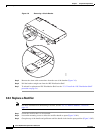
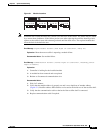
4.2.1 Alarm Interface Board and Connections
4.2.1 Alarm Interface Board and Connections
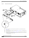
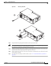
The alarm interface board is the main connection point for external communication inputs. The board is
located inside the controller and can be accessed by removing the front controller cover and then sliding
out the controller tray to expose the alarm connections (located on the right-hand side).
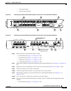
Alarm connections are made at the terminal block located on the Alarm/Interface PC board. The green
connectors can be easily removed for ease in installing the wires into the connector; 22 AWG (0.34mm²)
wire is recommended for connecting alarms to the alarm output terminals (Figure 2-21 on page 2-24).
External connections are Form C relay which can be monitored either Normally Closed or Normally
Open. The four alarms are numbered 1 through 4. (Refer to Table 2-6 on page 2-23).
Note All alarm connections are for the unpowered state. When the power is off the NC is normally closed and
when the power is on, the NC is open.
The following is a list of alarm board connections including descriptions and cabling:
• Alarms - Up to four Form C alarm contacts for remote signaling
• Load fuse and breaker monitoring
• RS232 Interface - External communications port (not utilized in this application)
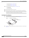
4.2.2 Basic Controller Functions
The following section contains basic controller functions including starting the controller, adding
modules, and removing modules from the system.
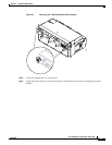
4.2.2.1 Start the Controller
When power is applied to the controller:
Step 1 The controller will spend several minutes analyzing the system and testing all addresses for connected
rectifier modules. The green LED on the controller will blink. No alarms will be raised during this
period.
Step 2 When the controller finds a module it will add it to the inventory.
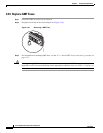
4.2.2.2 Add Modules
When a rectifier is added to the system it will remain off until the controller detects it.
Step 1 When a rectifier is added to the system, its output voltage will walk-in, increasing up to its default
setting. This will occur within 60 seconds.
Step 2 The controller constantly scans for new modules, but it may take a few minutes to recognize an inserted
module.