


2-25
Cisco AC/DC Power System User Guide, R1.0
May 2006
Chapter 2 System Installation
2.5.1 Install GMT Fuse Connections
2.5.1 Install GMT Fuse Connections
Load connections to the GMT fuse panel are made using spring loaded terminals that do not require the
use of connection lugs.
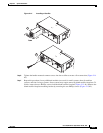
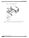
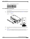
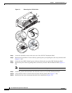
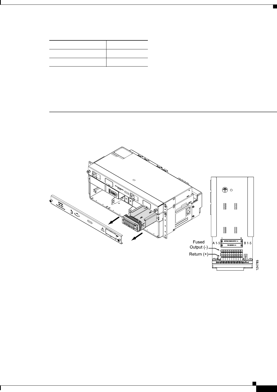
Step 1 Locate the GMT fuse connections by removing the controller faceplate (Figure 2-19) and sliding the
GMT drawer out (Figure 2-22).
Figure 2-22 GMT Drawer
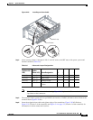
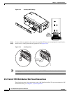
Step 2
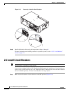
Route the GMT load-and-return cabling from the rear of the system shelf (leaving enough of a service
loop to allow the drawer to slide out) through the fuse panel channel and secure using the supplied
tie-downs.
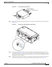
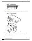
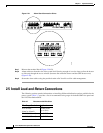
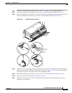
Step 3 Connect the wires to the appropriate terminal by using a flat screwdriver to open the terminal
(Figure 2-23) and inserting the appropriate cable into the spring-loaded terminals. Terminals correspond
to fuses: Side A (1-5) and Side B (1-5) from left to right (viewed from the front of the system).
14 AWG (2.5mm²) 10A GMT Fuses
14 AWG (2.5mm²) 15A GMT Fuses
Table 2-7 Recommended Wire Sizes (continued)
Wire Gauge Stranded Applications