


2-24
Cisco AC/DC Power System User Guide, R1.0
May 2006
Chapter 2 System Installation
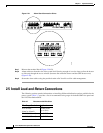
2.5 Install Load-and-Return Connections
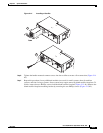
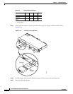
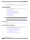
Figure 2-21 Alarm Board Connection Points
Step 7 Reinsert the terminal block (Figure 2-20 #3).
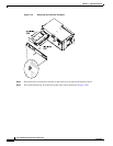
Step 8 Alarm cables run from the rear of the system shelf (leaving enough of a service loop to allow the drawer
to slide out) through the access window (between the controller drawer and the GMT drawer area)
(Figure 2-20).
Step 9 Secure the alarm cables using the provided strain relief tie-offs to aid in cable management.
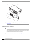
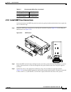
2.5 Install Load-and-Return Connections
The following section contains information on installing different distribution options available for the
power system. Table 2-7 provides a list of recommended wire gauges for both the GMT fuse panel and
the 1 RU Distribution Shelf.
124764
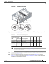
Table 2-7 Recommended Wire Sizes
Wire Gauge Stranded Applications
10 to 8 AWG
(6mm² to 10mm²)
Breaker Load
(up to 30A)
22 AWG (0.34mm²) 2A GMT Fuses
18 AWG (0.75mm²) 5A GMT Fuses