


2-21
Cisco AC/DC Power System User Guide, R1.0
May 2006
Chapter 2 System Installation
2.4.1 Install the Alarm Cable
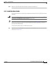
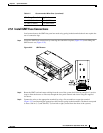
Step 8 Replace the 1 RU Distribution Shelf faceplate and tighten the thumbscrews.
2.4.1 Install the Alarm Cable
The following explains how to install alarm communication cabling to the Cisco AC/DC Power System
Controller.
Warning
Connect the unit only to DC power source that complies with the safety extra-low voltage (SELV)
requirements in IEC 60950 based safety standards.
Statement 1033
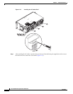
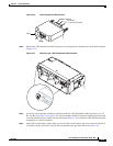
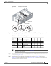
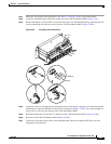
Note Alarm cables run from the rear right of the shelf through the power shelf (Figure 2-20) to the front alarm
interface board connectors; remove the controller faceplate and slide the controller tray forward to
access the alarm interface board.
To install alarm cabling to the Cisco AC/DC Power System:
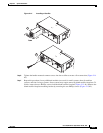
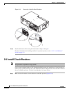
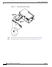
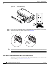
Step 1 Remove the system shelf faceplate (by loosening the two front thumbscrews) to access the controller
sliding drawer (Figure 2-19).