


3-6
Cisco AC/DC Power System User Guide, R1.0
May 2006
Chapter 3 Component Replacement
3.2.3 Replace Circuit Breakers
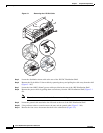
• J8 terminal block (Figure 3-4 or Figure 3-5 #4)
• J1 Ethernet cable (Figure 3-4 or Figure 3-5 #5)
• J1 terminal block (Figure 3-4 or Figure 3-5 #6)
Step 14 Reconnect the alarm cable connections (Figure 3-4 or Figure 3-5 #2).
• –J16 terminal block
• –J15 terminal block
• –J14/J13 terminal blocks
Step 15 Slide the controller tray back into the system shelf.
Step 16 Replace the controller faceplate by attaching it to the system shelf with the two front thumbscrews.
Step 17 After installing the controller, the controller and rectifier LEDs will blink. It may take a few minutes for
the controller to communicate with all rectifiers. At this point, all rectifier output voltages will return to
the programmed level. During this syncronization period output will not be affected.
3.2.3 Replace Circuit Breakers
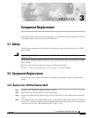
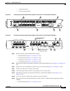
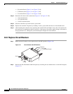
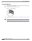
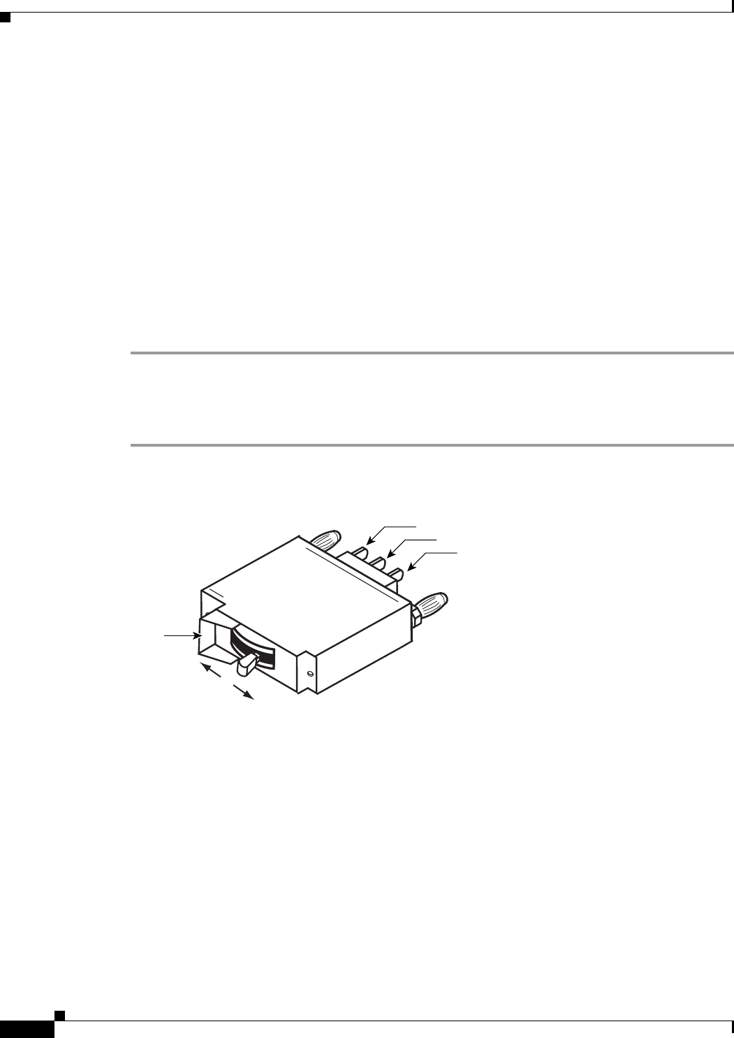
Step 1 Make certain all breakers to be replaced are in the OFF position (Figure 3-6).
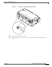
Figure 3-6 Circuit Breaker On/Off Positions
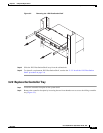
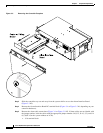
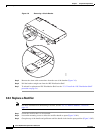
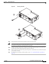
Step 2 Remove the 1RU Distribution Shelf faceplate by loosening the two thumbscrews on the shelf faceplate
(Figure 3-7).
Common
On
Hood
Off
Not Used
Normally Closed
124766