


46-2
Cisco Catalyst Switch Module 3110 and 3012 for IBM BladeCenter Software Configuration Guide
OL-12189-01
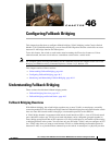
Chapter 46 Configuring Fallback Bridging
Understanding Fallback Bridging
acts like a port on a router, but it is not connected to a router. A routed port is not associated with a
particular VLAN, does not support VLAN subinterfaces, but behaves like a normal routed port. For more
information about SVIs and routed ports, see Chapter 10, “Configuring Interface Characteristics.”
A bridge group is an internal organization of network interfaces on a switch. You cannot use bridge
groups to identify traffic switched within the bridge group outside the switch on which they are defined.
Bridge groups on the switch function as distinct bridges; that is, bridged traffic and bridge protocol data
units (BPDUs) are not exchanged between different bridge groups on a switch.
Fallback bridging does not allow the spanning trees from the VLANs being bridged to collapse. Each
VLAN has its own spanning-tree instance and a separate spanning tree, called the VLAN-bridge
spanning tree, which runs on top of the bridge group to prevent loops.
The switch creates a VLAN-bridge spanning-tree instance when a bridge group is created. The switch
runs the bridge group and treats the SVIs and routed ports in the bridge group as its spanning-tree ports.
These are the reasons for placing network interfaces into a bridge group:
• To bridge all nonrouted traffic among the network interfaces making up the bridge group. If the
packet destination address is in the bridge table, the packet is forwarded on a single interface in the
bridge group. If the packet destination address is not in the bridge table, the packet is flooded on all
forwarding interfaces in the bridge group. A source MAC address is learned on a bridge group only
when the address is learned on a VLAN (the reverse is not true). Any address that is learned on a
stack member is learned by all switches in the stack.
• To participate in the spanning-tree algorithm by receiving, and in some cases sending, BPDUs on
the LANs to which they are attached. A separate spanning-tree process runs for each configured
bridge group. Each bridge group participates in a separate spanning-tree instance. A bridge group
establishes a spanning-tree instance based on the BPDUs it receives on only its member interfaces.
If the bridge STP BPDU is received on a port whose VLAN does not belong to a bridge group, the
BPDU is flooded on all the forwarding ports of the VLAN.
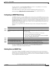
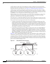
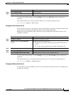
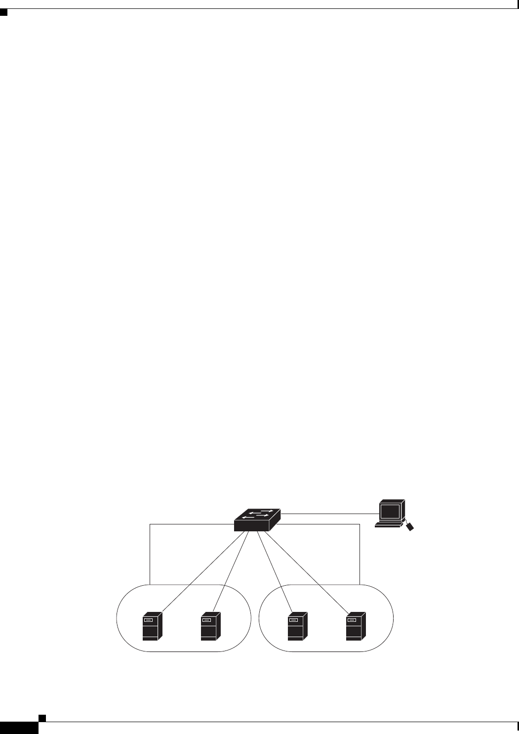
Figure 46-1 shows a fallback bridging network example. The switch has two ports configured as SVIs
with different assigned IP addresses and attached to two different VLANs. Another port is configured as
a routed port with its own IP address. If all three of these ports are assigned to the same bridge group,
non-IP protocol frames can be forwarded among the end stations connected to the switch even though
they are on different networks and in different VLANs. IP addresses do not need to be assigned to routed
ports or SVIs for fallback bridging to work.
Figure 46-1 Fallback Bridging Network Example
201789
Blade
server A
Host C
SVI 1172.20.128.1 172.20.129.1
Layer 3 switch
Routed port
172.20.130.1
SVI 2
VLAN 20
Blade
server B
VLAN 30