


37-23
Cisco Catalyst Switch Module 3110 and 3012 for IBM BladeCenter Software Configuration Guide
OL-12189-01
Chapter 37 Configuring EtherChannels and Link-State Tracking
Understanding Link-State Tracking
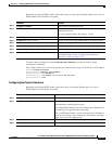
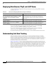
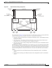
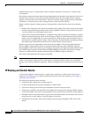
Figure 37-6 Typical Link-State Tracking Configuration
The configuration in Figure 37-6 ensures that when server NIC adapter teaming is used, the traffic flow
continues uninterrupted when the uplink connection to a distribution switch is lost.
• The blade switches in the enclosure are connected to distribution switch 1 and distribution switch 2
through port channels.
• Link-state group 1 is the primary link from all the blade servers in the enclosure (blade server 1
through blade server n) to distribution switch 1 through port channel 1.
• Link-state group 2 is the secondary (backup) links from all the blade servers to distribution switch 2
through port channel 2.
The blade servers can choose which Ethernet server interfaces are active. To balance the network traffic
flow, some Ethernet interfaces in link-state group 1 and some Ethernet interfaces in link-state group 2
are active. For example, when half of the Ethernet server interfaces connected to blade switch 1 are active
and the remaining interfaces connected to blade server 2 are active. the traffic flow can be divided as
follows:
• Traffic from half of the active Ethernet interfaces flows through blade switch 1 to distribution
switch 1.
• Traffic from the remaining active Ethernet interfaces flows through blade switch 2 to distribution
switch 2.
Link-state
group 2
Link-state
group 1
Blade
switch 1
Blade
switch 2
201917
Layer 3 link
Enclosure
Blade
server
1
Blade
server
2
Blade
server
n – 1
Blade
server
n
Distribution
switch 1
Distribution
switch 2
Link-state
group 1
(Port-channel 1)
Link-state
group 2
(Port-channel 2)