


19-6
Cisco Catalyst Switch Module 3110 and 3012 for IBM BladeCenter Software Configuration Guide
OL-12189-01
Chapter 19 Configuring Optional Spanning-Tree Features
Understanding Optional Spanning-Tree Features
How CSUF Works
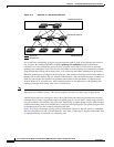
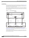
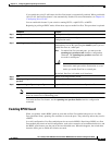
CSUF ensures that one link in the stack is elected as the path to the root. As shown in Figure 19-5, the
stack-root port on Switch 1 provides the path to the root of the spanning tree. The alternate stack-root
ports on Switches 2 and 3 can provide an alternate path to the spanning-tree root if the current stack-root
switch fails or if its link to the spanning-tree root fails.
Link 1, the root link, is in the spanning-tree forwarding state. Links 2 and 3 are alternate redundant links
that are in the spanning-tree blocking state. If Switch 1 fails, if its stack-root port fails, or if Link 1 fails,
CSUF selects either the alternate stack-root port on Switch 2 or Switch 3 and puts it into the forwarding
state in less than 1 second.
Figure 19-5 Cross-Stack UplinkFast Topology
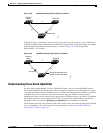
When certain link loss or spanning-tree events occur (described in the “Events that Cause Fast
Convergence” section on page 19-7), the Fast Uplink Transition Protocol uses the neighbor list to send
fast-transition requests to stack members.
The switch sending the fast-transition request needs to do a fast transition to the forwarding state of a
port that it has chosen as the root port, and it must obtain an acknowledgement from each stack switch
before performing the fast transition.
Switch 1
Spanning-
tree root
Backbone
Blade switch stack
StackWise Plus
port connections
201790
Switch 2 StackWise Plus
port connections
Forward
Link 1
(Root link)
Link 2
(Alternate
redundant
link)
Link 3
(Alternate
redundant
link)
100 or 1000 Mbps 100 or 1000 Mbps 100 or 1000 Mbps
Forward
Forward
Switch 3 StackWise Plus
port connections
Stack-root port
Alternate stack-
root port
Alternate stack-
root port