


40-3
Cisco Catalyst Switch Module 3110 and 3012 for IBM BladeCenter Software Configuration Guide
OL-12189-01
Chapter 40 Configuring HSRP
Understanding HSRP
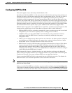
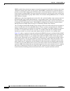
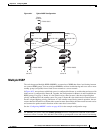
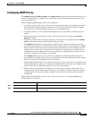
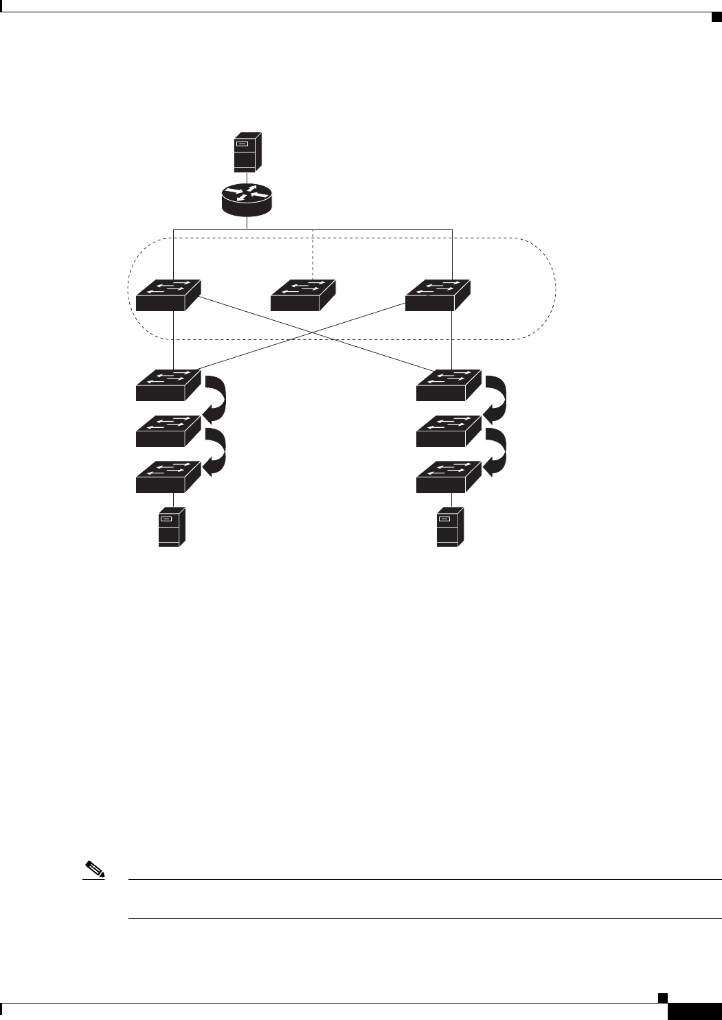
Figure 40-1 Typical HSRP Configuration
Multiple HSRP
The switch supports Multiple HSRP (MHSRP), an extension of HSRP that allows load sharing between
two or more HSRP groups. You can configure MHSRP to achieve load-balancing and to use two or more
standby groups (and paths) from a blade server network to a server network.
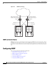
In Figure 40-2, one enclosure with blade servers is configured for Router A, and the other enclosure with
blade servers is configured for Router B. Together, the configuration for Routers A and B establish two
HSRP groups. For group 1, Router A is the default active router because it has the assigned highest
priority, and Router B is the standby router. For group 2, Router B is the default active router because it
has the assigned highest priority, and Router A is the standby router. During normal operation, the two
routers share the IP traffic load. When either router becomes unavailable, the other router becomes active
and assumes the packet-transfer functions of the router that is unavailable.
See the “Configuring MHSRP” section on page 40-9 for the example configuration steps.
Note For MHSRP, you need to enter the standby preempt interface configuration command on the HSRP
interfaces so that if a router fails and then comes back up, preemption occurs and restores load sharing
Blade
server B
172.20.130.5
172.20.128.32
Blade
server A
172.20.128.55
172.20.128.1 172.20.128.3 172.20.128.2
Virtual
router
Active
router
Standby
router
Router A Router B
201787
Blade
server C