


A-5
Cisco AS5350XM and Cisco AS5400XM Universal Gateways Card Installation Guide
78-17406-01
Appendix A Cabling Specifications
2-Port and 4-Port T1 or E1 Feature Card Cable and Port Pinouts
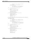
Table A-9 lists the RJ-45-to-RJ-45 T1 cable pinouts.
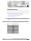
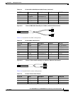
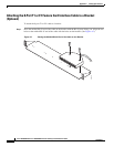
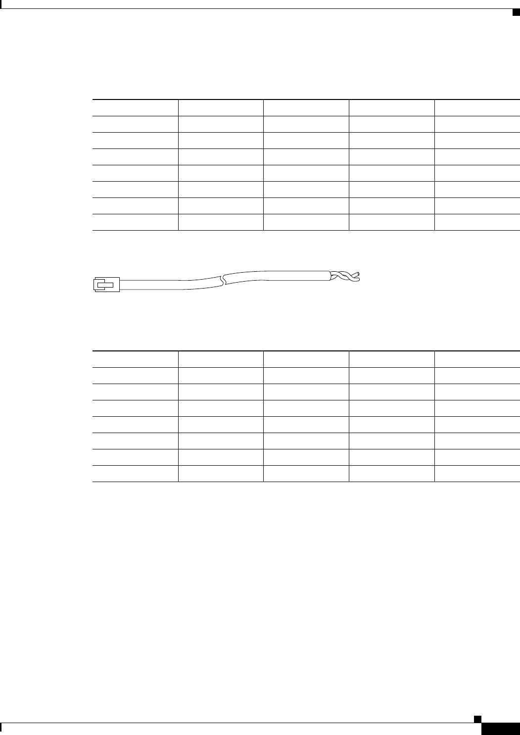
Figure A-5 RJ-45 to Bare Wire Cable Assembly
Table A-10 lists the RJ-45 to bare wire cable pinouts.
Table A-9 RJ-45-to-RJ-45 T1 Cable Pinouts
RJ-45 Pin Signal Description Direction RJ-45 T1 Pin
Shield Ground Shell/Braid Shield
J1-1 RX Tip Twisted Pair #1 <— J2-1
J1-2 RX Ring Twisted Pair #1 <— J2-2
J1-3 RX Shield
J1-4 TX Tip Twisted Pair #2 —> J2-4
J1-5 TX Ring Twisted Pair #2 —> J2-5
J1-6 TX Shield
35646
J1
Table A-10 RJ-45 to Bare Wire Cable Pinouts
RJ-45 Pin Signal Description Direction Bare
Shield Ground Braid
J1-1 RX Tip Twisted Pair #1 <— WIRE-1
J1-2 RX Ring Twisted Pair #1 <— WIRE-2
J1-3 RX Shield
J1-4 TX Tip Twisted Pair #2 —> WIRE-3
J1-5 TX Ring Twisted Pair #2 —> WIRE-4
J1-6 TX Shield