


A-12
Cisco AS5350XM and Cisco AS5400XM Universal Gateways Card Installation Guide
78-17406-01
Appendix A Cabling Specifications
CT3 Feature Card Cable and Port Pinouts
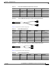
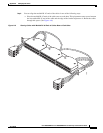
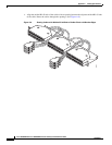
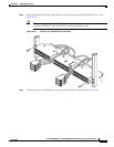
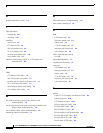
Step 5 Insert the 36-pin cable connector into the 36-pin port on the 8-port T1 or E1 feature card. Tighten the
captive screws on the 36-pin cable connector to secure the cable to the feature card. (See Figure A-11.)
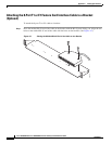
Figure A-11 Connecting the 36-Pin Cable Connector to an 8-Port T1 or E1 Feature Card
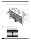
CT3 Feature Card Cable and Port Pinouts
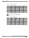
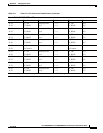
Table A-12 lists the CT3 feature card port pinouts.
35062
Table A-12 CT3 Feature Card Port Pinouts
Pin Description
Receiver port (on the left)
1Rx signal
2 Ground
Transmitter port
1Tx signal
2 Ground