


1-6
Cisco MDS 9100 Series Hardware Installation Guide
OL-16187-01
Chapter 1 Product Overview
Power Supplies
Power Supplies
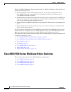
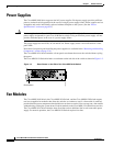
The Cisco MDS 9100 Series supports dual AC power supplies. Each power supply provides sufficient
power to maintain switch operation in the event of a single power supply failure. Power supplies are hot
swappable and can be individually replaced without disruption to the system. (See the “Power
Specifications” section on page B-2.)
Caution Power supplies for the Cisco 9100 Series look similar but they differ slightly. Be sure to use the correct
power supply designated for your Cisco 9100 Series switch. Using an incorrect power supply will not
provide redundant power in the case of a power supply failure.
The power supply has two LEDs, AC ok and DC ok. Power supply status is also indicated on a front
panel LED.
Procedures for replacing and installing the power supplies are available in the “Removing and Installing
Components” section on page 2-26.
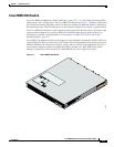
The Cisco MDS 9124 Switch includes a front panel reset button that resets the switch without cycling
the power.
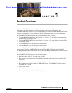
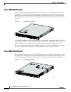
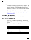
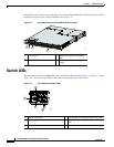
The Cisco MDS 9134 Switch includes a reset button on the left side of the switch as shown in Figure 1-5.
Figure 1-5 Reset Button on the Side of the Cisco MDS 9134 Switch
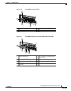
Fan Modules
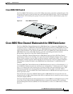
The Cisco MDS 9140 Switch, the Cisco MDS 9134 Switch, and the Cisco MDS 9120 Switch support
two hot-swappable fan modules that allow the switches to continue to run if a fan module is removed,
provided that the preset temperature thresholds have not been exceeded. You can swap out a fan module
without having to bring the system down. Each fan module on the Cisco MDS 9134 Switch has two fans.
The Cisco MDS 9124 Switch includes three fixed fans and an additional fan in each removable power
supply. For normal operation, the Cisco MDS 9124 Switch requires four fans.
184098
Reset button