


1-10
Cisco MDS 9100 Series Hardware Installation Guide
OL-16187-01
Chapter 1 Product Overview
Switch LEDs
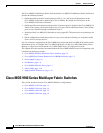
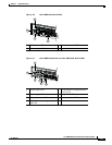
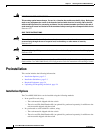
Only the first port in each four-port group can be an Inter-Switch Link (ISL). If the first port is an ISL,
the other three ports in the group are disabled. See Figure 1-8.
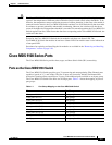
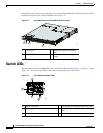
Figure 1-8 Cisco MDS 9140 and Cisco MDS 9120 Switch Ports
Switch LEDs
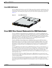
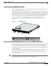
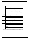
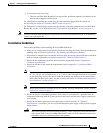
The front panel of the Cisco MDS 9100 Series includes the LEDs shown in Figure 1-9, Figure 1-10, and
Figure 1-11. You can use the LEDs on this panel to quickly identify system status.
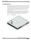
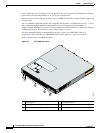
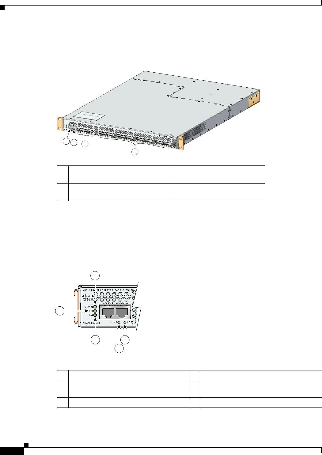
Figure 1-9 Cisco MDS 9134 Switch LEDs
1 Console port 3 Bandwidth optimized switching
ports
2 10/100 Ethernet management port 4 Host optimized switching port
groups
94180
1
2
3
4
184093
3
4
5
2
1
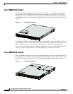
1 Switch status LED 4 10/100 Ethernet management port link LED
2 Power supply LED 5 10/100 Ethernet management port activity
LED
3 Fan module status LED