


2-4
Cisco MDS 9100 Series Hardware Installation Guide
OL-16187-01
Chapter 2 Installing the Cisco MDS 9100 Series
Preinstallation
• Ensure that circuits are sized according to local and national codes.
For North America, the 300-W power supplies require a 20-A circuit.
If you are using a 200- or 240-VAC power source in North America, the circuit must be protected
by a two-pole circuit breaker.
Caution To prevent loss of input power, ensure the total maximum loads on the circuits supplying
power to the switch are within current ratings for wiring and breakers.
• As you install and configure the switch, record the information listed in the “Site Planning and
Maintenance Records” section on page D-1.
• Use the following screw torques when installing the switch:
–
Captive screws: 4 in-lb
–
M3 screws: 4 in-lb
–
M4 screws: 12 in-lb
–
10-32 screws: 20 in-lb
–
12-24 screws: 30 in-lb
Required Equipment
Gather the following tools before beginning the installation:
• Number 1 Phillips screwdriver with torque capability
• 3/16-in. flat-blade screwdriver
• Tape measure and level
• ESD wrist strap or other grounding device
• Antistatic mat or antistatic foam
The following additional items (not found in the accessory kit) are required to ground the chassis:
• Grounding cable (6 AWG recommended), sized according to local and national installation
requirements; the required length depends on the proximity of the switch to proper grounding
facilities
• Crimping tool large enough to accommodate girth of lug
• Wire-stripping tool
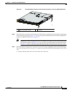
Unpacking and Inspecting the Switch
Caution When handling switch components, wear an ESD strap and handle modules by the carrier edges only.
An ESD socket is provided on the chassis. For the ESD socket to be effective, the chassis must be
grounded through the power cable, the chassis ground, or the metal-to-metal contact with a grounded
rack.
Tip Keep the shipping container in case the chassis requires shipping in the future.