


2-3
Cisco MDS 9100 Series Hardware Installation Guide
OL-16187-01
Chapter 2 Installing the Cisco MDS 9100 Series
Preinstallation
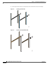
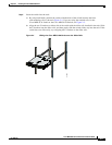
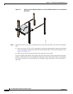
• In a two-post telco rack, using:
–
The telco and EIA Shelf Bracket Kit (an optional kit, purchased separately) in addition to the
front brackets shipped with the switch
For instructions on installing the switch using the rack-mount kit shipped with the switch, see
the“Installing the Switch in a Cabinet or Rack” section on page 2-5.
For instructions on installing the switch using the optional, separately purchased telco and EIA Shelf
Bracket Kit, see the “Cisco MDS 9000 Family Telco and EIA Shelf Bracket” section on page A-3.
Note The telco and EIA Shelf Bracket Kit is optional and is not provided with the switch. To order the kit,
contact your switch provider.
Installation Guidelines
Follow these guidelines when installing the Cisco MDS 9100 Series:
• Plan your site configuration and prepare the site before installing the switch. The recommended site
planning tasks are listed in Appendix D, “Site Planning and Maintenance Records.”
• Ensure there is adequate space around the switch to allow for servicing the switch and for adequate
airflow (airflow requirements are listed in Appendix B, “Technical Specifications”).
• Ensure the air-conditioning meets the heat dissipation requirements listed in Appendix B,
“Technical Specifications.”
• Ensure the cabinet or rack meets the requirements listed in Appendix A, “Cabinet and Rack
Installation.”
Note If the front cabinet mounting rails are not offset from the front door or bezel panel by a minimum
of 3 in. (7.6 cm), and a minimum of 5 in. (12.7 cm) if cable management brackets are installed
on the front of the chassis, the chassis should be mounted rear-facing to ensure the minimum
bend radius for fiber-optic cables. See the“Installing the Switch in a Cabinet with Insufficient
Front Clearance” section on page 2-11.
Note Jumper power cords are available for use in a cabinet. For more information, see the “Jumper
Power Cord” section on page C-5.
• Ensure the chassis is adequately grounded. If the switch is not mounted in a grounded rack, we
recommend connecting both the system ground on the chassis and the power supply ground to an
earth ground.
• Ensure the site power meets the power requirements listed in Appendix B, “Technical
Specifications.” If available, you can use an uninterruptible power supply (UPS) to protect against
power failures.
Caution Avoid UPS types that use ferroresonant technology. These UPS types can become unstable
with systems such as the Cisco MDS 9000 Family, which can have substantial current draw
fluctuations because of fluctuating data traffic patterns.