


2-24
Cisco MDS 9100 Series Hardware Installation Guide
OL-16187-01
Chapter 2 Installing the Cisco MDS 9100 Series
Starting Up the Switch
Note Customers who require compliance to GR-1089-CORE bonding and grounding requirements, must use
the ground conductor.
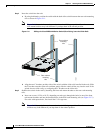
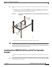
To attach the grounding lug and cable to the chassis, follow these steps:
Step 1 Use a wire-stripping tool to remove approximately 0.75 in. (19 mm) of the covering from the end of the
grounding cable.
Step 2 Insert the stripped end of grounding cable into the open end of the grounding lug.
Step 3 Use the crimping tool to secure the grounding cable in the grounding lug.
Step 4 Remove the adhesive label from the grounding pad on the chassis.
Step 5 Place the grounding lug against the grounding pad so that there is solid metal-to-metal contact, and insert
the two M4 screws with washers through the holes in the grounding lug and into the grounding pad.
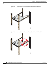
Step 6 Ensure that the lug and cable do not interfere with other equipment.
Step 7 Prepare the other end of the grounding cable and connect it to an appropriate grounding point in your
site to ensure adequate earth ground.
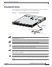
Starting Up the Switch
This section provides instructions for powering up the switch and verifying component installation.
Caution During this procedure, wear grounding wrist straps to avoid ESD damage to the switch.
Note Do not connect the MGMT 10/100 Ethernet port to the LAN until the initial switch configuration has
been performed. For instructions on configuring the switch, see the Cisco MDS 9000 Family CLI
Configuration Guide. For instructions on connecting to this port, see the “Connecting the Console Port”
section on page 3-1.
To power up the switch and verify hardware operation, follow these steps:
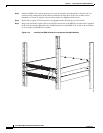
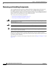
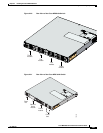
Step 1 Verify that both power supplies and fan modules are installed and tighten any loose captive screws.
Step 2 Verify that the power switches on both power supplies are off. Then plug the power cables into the power
supplies and arrange the cables so that they cannot be accidentally pulled out.
Note Depending on the outlet receptacle on your power distribution unit, you may need the optional
jumper power cord to connect the Cisco MDS 9100 Series Switch switch to your outlet
receptacle. See the “Jumper Power Cord” section on page C-5.
Step 3 Connect the other end of the power cables to an AC power source.