


Chapter 4
Advanced Configuration
25
4-Port SSL/IPSec VPN Router
Port Receive Packet Count The number of packets
received is displayed.
Port Receive Packet Byte Count The number of packet
bytes received is displayed.
Port Transmit Packet Count The number of packets
transmitted is displayed.
Port Transmit Packet Byte Count The number of packet
bytes transmitted is displayed.
Port Packet Error Count The number of packet errors is
displayed.
Click Refresh to retrieve the most recent settings and
statistics.
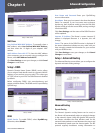
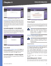
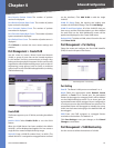
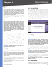
Port Management > Create VLAN
Use this screen to create a Virtual Local Area Network
(VLAN), a group of ports that can be located anywhere
in the network, but they communicate as though they
belong to the same physical segment. VLANs can be easily
organized to reflect departmental groups (such as sales or
engineering), usage groups (such as e-mail), or multicast
groups (such as users of multimedia applications, including
videoconferencing).
Port Management > Create VLAN
Create VLAN
The Router supports up to 15 VLANs, excluding the default
VLAN.
Enable VLAN Select Enable VLAN to use the VLAN
feature.
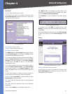
When the VLAN feature has been enabled, the default
VLAN ID 1 will be displayed and applied. You can create a
single VLAN or create multiple VLANs by range.
VLAN ID Enter a VLAN ID number from 2 to 4094. (The
default VLAN ID 1 is assigned to untagged frames received
on the interface.) Click Add VLAN to add the single
VLAN ID.
VLAN ID Range Enter the starting and ending port
numbers of the VLAN ID Range. Then click Add Range.
VLAN ID and Description All of the VLAN IDs that you
have set up and the VLAN descriptions you have defined
for each VLAN on the VLAN Membership screen will be
applied and displayed on the Create VLAN screen.
Delete VLAN To delete a VLAN, select it from the list and
click Delete VLAN.
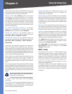
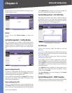
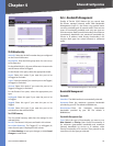
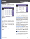
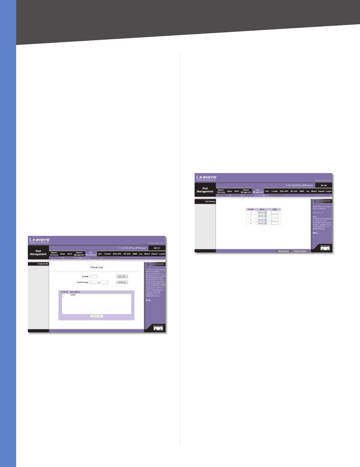
Port Management > Port Setting
Select the mode and configure the Port VLAN Identifier
(PVID) for each LAN port of the Router.
Port Management > Port Setting
Port Setting
Port ID The Router’s LAN ports are numbered 1 to 4.
Mode Select the appropriate mode: General, Access
(default), or Trunk. For a General port, the transmitted
frames can be tagged or untagged, and it will be defined
on the VLAN Membership screen. For an Access port, the
transmitted frames will be untagged. A port configured as
a Trunk port acts as a direct link between two switches. The
transmitted frames will be tagged to identify the source
VLAN, but the frames belonging to the default VLAN will
be untagged.
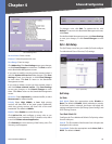
PVID Enter the PVID assigned to untagged frames
received on the interface. The default is 1.
Click Save Settings to save your changes, or click Cancel
Changes to undo them.
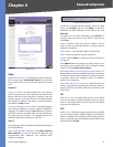
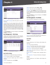
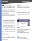
Port Management > VLAN Membership
Use this screen to define the members of a VLAN.