


If the server is powered on, the resources of the selected adapter card appear in the tabbed menu below the
Adapter Cards area.
Step 5
In the tabbed menu below the Adapter Cards area, click the VM FEXs tab.
Step 6
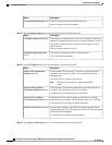
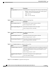
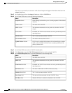
In the Virtual FEXs area, review the following information:
DescriptionName
Opens a dialog box that allows you to view the properties for the selected
VM FEX.
Properties button
The name of the VM FEX.Name column
The maximum transmission unit, or packet size, that this VM FEX
accepts.
MTU column
If enabled, the VM FEX uses the class of service provided by the host
operating system.
CoS column
The VLAN associated with the VM FEX.VLAN column
The mode for the associated VLAN.VLAN Mode column
If NIV mode is enabled for the adapter, this column displays whether
traffic on this VM FEX will fail over to a secondary interface if the
primary interface fails.
Uplink Failover column
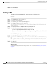
Step 7
In the Virtual FEXs area, select a VM FEX from the table.
Step 8
Click Properties to open the VM FEX Properties dialog box for the selected VM FEX.
Step 9
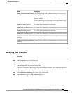
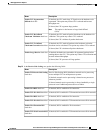
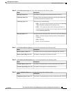
In the General Properties area, review the information in the following fields:
DescriptionName
The name of the VM FEX.Name field
The maximum transmission unit, or packet size, that this VM FEX
accepts.
MTU field
If enabled, the VM FEX uses the class of service provided by the host
operating system.
Trust Host CoS field
The order in which this VM FEX will be used, if any.PCI Order field
The VLAN associated with the VM FEX.Default VLAN field
The data rate limit associated with this VM FEX, if any.Rate Limit field
Whether PXE boot is enabled or disabled for this VM FEX.PXE Boot field
Cisco UCS C-Series Servers Integrated Management Controller GUI Configuration Guide, Release 1.4
32 OL-23489-08
Managing Network Adapters
Viewing Virtual FEX Properties