


Technical Reference Guide
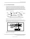
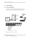
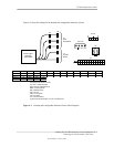
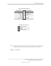
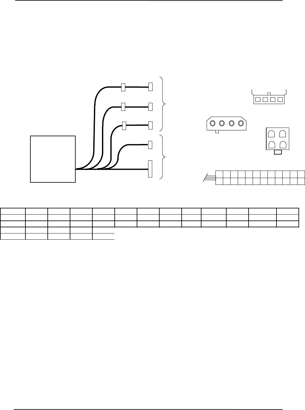
Figure 6-3 shows the cabling for the desktop and configurable minitower systems.
P1
P8
P3
P7
P6
P4
P5
P2
Power Supply
Assembly
(PN 243890)
P7, P8
4 3 2 1
To
Drive
Assemblies
P2, P4-6
1 2 3 4
P3
4 3
2 1
To
System
Board
P1
18
1
9
21
8
20
13
10
22
6
7
19
3
15
4
16
5
17
2
14
11
23
12
24
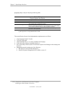
Conn. Pin 4 Pin 6 Pin 8 Pin 10 Pin 12 Pin 1 Pin 2 Pin 3 Pin 5 Pin 7 Pin 9 Pin 11
P1 +3.3 +3.3 RTN +5 RTN +5 RTN FO +5 x +3.3 x Au +12 Au FC
P1 [1] +3.3 -12 RTN -5
P2, 4-7 +5 GND GND +12
PS On RTN RTN RTN +5 +5 +3.3 FS
+12.8 P3 GND +12.8 GND
NOTES:
le.
round)
sense
ed
[1] This row represents pins 13 - 24 of connector P1.
igure 6–3. Desktop and Configurable Minitower Power Cable Diagram
Connectors not shown to sca
All + and - values are VDC
.
RTN = Return (signal g
GND = Power ground
RS = Remote
FO = Fan off
FSpd = Fan spe
FS = Fan Sink
FC = Fan Command
F
Compaq Evo and Workstation Personal Computers
Featuring the Intel Pentium 4 Processor
Second Edition - January 2003
6-7