


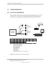
Chapter 6 Power and Signal Distribution
Chassis
Fan
PCI Slot Exp.
Edge Connector
USB Conn.
Conn. P24
Microphone In
USB Data 3, USB Data 4
Headphones Out
A udio/USB
I/O Board
Assembly [2]
Audio
Conn. P23
Conn.
P3
Pwr Btn, Pwr/HD LED
Power On
Power On/Off
Audio
Conn. P7
Mouse
Kybd.
Conn. J68
Dsk.
Conn. P10
Mouse
Keyboard
Sec. IDE
Conn. P21
System
Board
(PCA #011345 or
011348)
Conn.
P8
Fan
PWR
Conn.
P6
Conn.
P124
Conn.
P125
Cover Lock
Solenoid
(Optional)
Audio
Conn.
P5 [1]
Graphics
Controller
AGP
Bus
AGP
Connector
Pri. IDE
Conn. P20
Conn.
P1
12.8 Vcpu
Fan Cntrl., PS On
IDE
Data, Cntl
IDE
Hard Drive
IDE I/F
CD-ROM
5, 12 VDC
5, 12 VDC
Diskette Drive
Dskt.
L/R Audio
Data, Cntl
5, 12 VDC
3/5/12 VDC, 3/5AUX
Power
Supply
Assembly
Cover Sensor [3]
HD Activity
PCI Slot Exp.
Card
PCI Bus
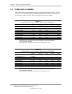
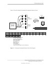
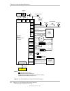
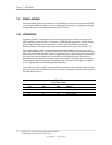
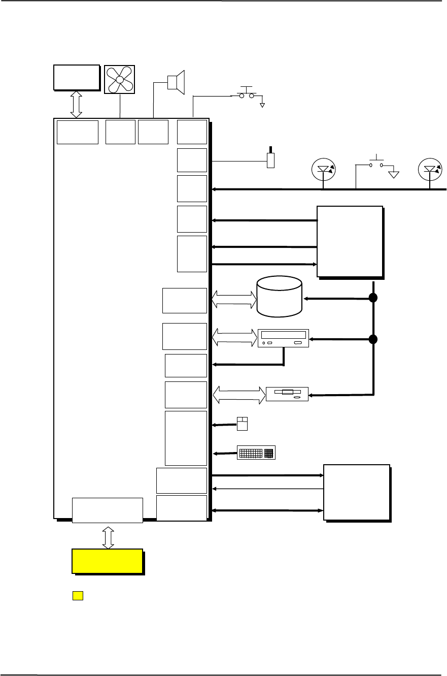
N OTES:
orkstation systems.
[3] Sensor switch installed on desktop only.
igure 6–6. Desktop/Minitower Signal Distribution Diagram
[1] Configurable minitower only.
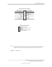
[1] Header pinout shown in Figure 6-7.
[2] Optional on Evo systems. Standard on W
F
Compaq Evo and Workstation Personal Computers
Featuring the Intel Pentium 4 Processor
Second Edition- January 2003
6-10