


Chapter 2 System Overview
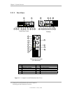
2.3.3 BOARD LAYOUTS
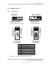
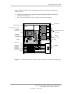
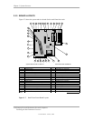
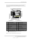
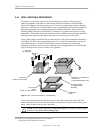
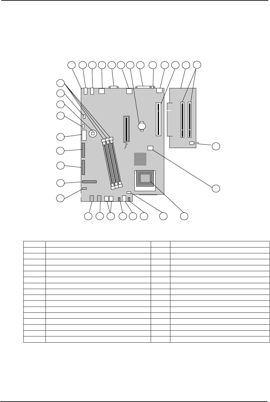
Figure 2-7 shows the system and riser boards for the small form factor unit.
Item
Description
Item Description
1 System board 17 Processor fan connector
2 Audio line in jack 18 Hard drive activity LED
3 Audio line out jack 19 Power button
4 USB connectors (2) 20 Power LED
5 Serial port A 21 USB ports (2)
6 Network interface connector 22 Audio headphones output jack
7 Battery 23 Audio microphone input jack
8 Parallel port 24 CD-ROM audio input connector
9 Serial port B 25 Diskette drive connector
10 Top: Mouse conn.; Bottom: keyboard conn. 26 Secondary IDE connector
11 Riser board slot 27 Primary IDE connector
12 Riser board 28 Power supply connector
13 PCI slot connectors (2) 29 Internal speaker connector
14 Hood (cover) sensor switch 30 CMOS clear button
15 Processor power connector 31 Hood (cover) lock solenoid connector
16 Processor socket (mPGA478) 32 DIMM sockets
NOTE:
Third DIMM socket present on PC133-based boards.
System Board PCA# 011466-101 or 011351-001
Riser Board SP# 252298-001
3
2
8
11
12
13
10
18
9
20
6
7
17
14
16
19
28
21
31
29
26
22
23
24
4
5
1
25
27
15
30
32
Figure 2–7. Small Form Factor Board Layouts
Compaq Evo and Workstation Personal Computers
Featuring the Intel Pentium 4 Processor
Second Edition – January 2003
2-10