Generating Label Formats
66 E-Class DPL Programmer’s Manual
Placing a 0 (zero) in both c and d will cause the printer to use the default bar code ratio or module
size. Placing a 000 (zero) in the symbol height field causes the printer to use the default bar code
height.
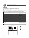
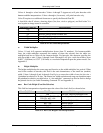
5. Images
An image record is used to print an image that is stored in a memory module. Images can be
printed only in rotation 1, (see Input Image Data <STX>I).
Field Valid Inputs Meaning
a
1 Fixed Value
b
YImage
c
1to9andAtoO
Width Multiplier
d
1to9andAtoO
Height Multiplier
eee
000 Fixed Value
ffff
0000 to 9999 Row
gggg
0000 to 9999,
see Appendix J. Column
jj…j
ASCII string, up to 16 characters followed by a termination
character.
Image Name
Table 8-11: Image Fields
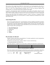
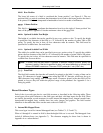
6. Graphics
Using graphics, the printer can produce lines, boxes, polygons, and circles. This function is
selected by entering an X in field b. The values entered in the data field determine the sizes and
shapes of the objects to be drawn. Forms can be created using shaded boxes, complex logos, or
even a simple diagonal line without the need to download a graphics file to the printer. The
following sub-sections describe how to generate each kind of graphic.
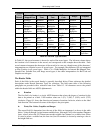
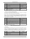
Lines and Boxes
Lines and boxes are drawn by values that determine column and row starting position, length,
width, and wall thickness of the line or box (see Appendix J). All measurements are interpreted
as inches/100 or millimeters/10, depending on the printer’s mode (see <STX>m). The data
field jj…j is used to describe the line or box dimensions.
Segment Valid Inputs Meaning
a
1 Fixed value
b
XLine/Box
c
1 Fixed Value
d
1 Fixed Value
eee
000 Fixed Value
ffff
0000 to 9999 Row
gggg
0000 to 9999,
see Appendix J. Column
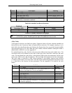
jj...j
Lhhhvvv - Line Drawing
lhhhhvvvv - Line Drawing
Bhhhvvvtttsss - Box Drawing
Bhhhhvvvvttttssss - Box Drawing
Line *
Line **
Box ***
Box ****
Table 8-12: Line and Box Parameters


