


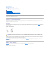

1. Remove the bezel (see "Removing the Bezel").
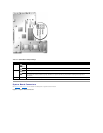
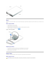
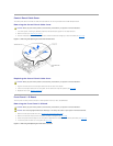
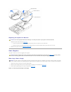
2. Loosen the three thumbscrews that secure the cover to the chassis (see Figure4-3).
3. Slide the back cover backward and grasp the cover at both ends.
4. Carefully lift the cover away from the system.
Figure 4-3. Removing the Cover
Replacing the Cover
1. Ensure that no tools or parts are left inside the system and that any cables are routed so that they will not be damaged by the cover.
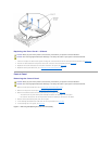
2. Align the cover with the cover alignment hooks on the sides of the chassis, and slide the cover forward (see Figure4-3).
3. Tighten the three thumbscrews that secure the cover to the chassis.
4. Replace the bezel (see "Replacing the Bezel").
Inside the System
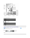
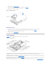
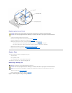
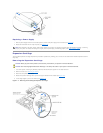
In Figure4-4, the covers and bezel are removed to provide an interior view of the system.
Figure 4-4. Inside the System
The system board holds the system's control circuitry and other electronic components. Several hardware options, such as the microprocessors and memory,
are installed directly on the system board. The expansion-card cage accommodates up to three full-length PCI or PCI-X expansion cards.
The system provides space for a 3.5-inch diskette drive and a CD drive. The CD/diskette drive tray connects to the controllers on the system board through the
SCSI backplane board. For more information, see "CD and Diskettes Drives."
The hard-drive bays provide space for up to five 1-inch SCSI hard drives. The hard drives connect to a controller on the system board or a RAID controller card
through the SCSI backplane board. For more information, see "Hard Drives."
During an installation or troubleshooting procedure, you may be required to change a jumper setting. For more information, see "Jumpers and Connectors."