


Replacing the Expansion-Card Cage
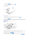
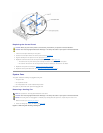
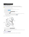
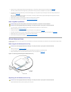
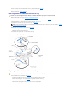
1. With the expansion-card cage lever in the upright position, carefully lower the cage into the chassis until it is aligned with the tabs on the chassis side
wall (see Figure4-11).
2. Rotate the expansion-card cage lever down until the handle is flush with the top of the cage, and the cage is secured in the chassis (see Figure4-11).
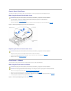
3. Reconnect all expansion-card cables.
4. Replace the cover (see "Replacing the Cover").
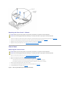
Expansion Cards
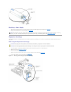
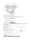
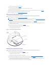
The system includes three expansion slots. The expansion cards are installed on the system's riser board (see Figure5-4 to identify the expansion slots).
Expansion Card Installation Guidelines
Use the following guidelines when installing expansion cards:
l You can install expansion cards of different operating speeds on the same bus; however, the bus will operate at the slowest operating speed of the
cards on that bus. For example, if one card on the bus has an operating speed of 33 MHz and the other card has an operating speed of 66 MHz, the bus
will only operate at 33 MHz.
l Wheninstallingabootcontrollerexpansioncard,suchasaRAIDorSCSIcontrollercard,installthebootcontrollercardinexpansionslot1.Thisposition
allows your operating system to properly use the boot controller card. For more information, see "PCI Bus Scan Order."
To identify expansion slots and PCI buses, see Figure5-4. Table4-1 lists the PCI bus and operating speed for each expansion-card slot.
PCI Bus Scan Order
The system's BIOS scans and numbers PCI buses and devices during startup. Expansion slots are scanned according to the host bus ordering, not by the slot
numbers. See Table4-2 for the order in which the expansion slots and embedded PCI devices are scanned. Figure5-4 provides a diagram of buses and
expansion slots.
Certain operating systems do not allow the PCI bus number of the system's boot controller to change after the operating system loads. Installing an
expansion card with its own PCI bridge chip in an expansion slot earlier in the PCI bus scan order than the boot controller can cause the renumbering of the
boot controller PCI bus number. To allow your operating system to properly use the boot controller expansion card, install the boot controller card, such as a
RAIDorSCSIcontrollercard,inexpansionslot1.
An additional factor affects the assignment of PCI bus numbers: an expansion card may have its own PCI bridge chip which requires the assignment of a bus
number for the card as well as one for the bridge. A particular expansion card may have two PCI bridge chips which would result in three sequential PCI bus
numbers all assigned in the same expansion slot.
If you install expansion cards, you may have some difficulty in directly determining the bus number of a controller on a particular expansion card. However, the
PCI bus scan order listed in Table4-2 can help determine the relative numbering of PCI buses within the expansion slots. For example, a PCI controller
residing in expansion slot 3 will never have a lower bus number than one in slot 2 because slot 2 precedes slot 3 in the scan order.
CAUTION: Before you perform this procedure, read the safety instructions in your System Information document.
CAUTION: See "Protecting Against Electrostatic Discharge" in the safety instructions in your System Information document.
NOTICE: To avoid damage to the system, keep the bottom of the expansion-card cage parallel to the system board, while lowering the cage into the
chassis.
Table 4-1.ExpansionSlotSpeeds
Slot
Bus
Operating Speed
1
1
Up to 100 MHz
2
1
l Slot 1 is not empty — up to 100 MHz
l Slot 1 is empty — up to 133 MHz
3
2
Up to 133 MHz
NOTE: If you are using expansion cards of different operating speeds, you should install the fastest card in slot 3 and the slowest card in slot 1.
Table 4-2.PCIBusScanOrder
Order
Device or Slot
1
Video
2
Embedded remote access components
3
Expansion slot 1
4
Expansion slot 2
5
Expansion slot 3
6
Integrated NIC 1