


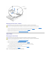
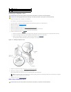
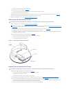

Replacing the Expansion-Card Riser Board
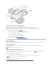
1. Replace the expansion-card riser board (see Figure4-13):
a. Align the riser board with the expansion-card cage's grounding tabs.
b. Slide the riser board toward the card-guidelatchbracketabout0.5inch.
c. Tighten the thumbscrew on the riser board.
d. Rotate the card-guide latch bracket back into position.
e. Tighten the thumbscrew on the card-guide latch bracket.
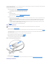
2. Install all expansion cards (see "Installing an Expansion Card").
3. Replace the expansion-card cage (see "Replacing the Expansion-Card Cage").
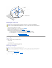
Memory Modules
Thesixmemorymoduleconnectorsonthesystemboardcanaccommodate256MBto6GBofregisteredmemorymodules.Thememorymoduleconnectorsare
arranged in pairs which consist of three banks.
Memory Upgrade Kits
The system is upgradable to 6 GB by installing combinations of 128-, 256-, 512-MB, and 1-GB registered DDR SDRAM modules. You can purchase memory
upgrade kits as needed.
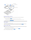
Memory Module Installation Guidelines
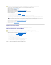
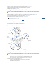
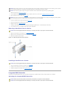
Memory module connectors are arranged in pairs, labeled A and B. Each pair of modules forms a single bank. See Figure5-3 to identify memory module
connectors on the system board.
When you install memory modules, follow these guidelines:
l You must install memory modules in matched pairs.
l Install identical memory modules in connectors A and B for bank 1 before installing modules in connectors for bank 2, and so on.
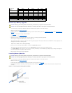
Table4-3 lists several sample memory configurations based on these guidelines.
CAUTION: Before you perform this procedure, read the safety instructions in your System Information document.
CAUTION: See "Protecting Against Electrostatic Discharge" in the safety instructions in your System Information document.
NOTE: The memory modules must be PC-1600 compliant.
Table 4-3.SampleMemoryModuleConfigurations