Chapter 7
7 - 2
Reviewing a sample CDN configuration
The two following diagrams illustrate how DNS query resolutions for
content delivery networks are processed by the 3-DNS Controller. In the
example, the content provider for www.download.siterequest.com has two
data centers, one in San Jose, California (see Figure 7.1), and one in
Washington, DC (see Figure 7.2 on page 7-3). The 3-DNS Controllers (in
the two data centers) use the Topology load balancing mode to direct the
DNS queries to the geographically closest virtual servers.
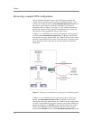
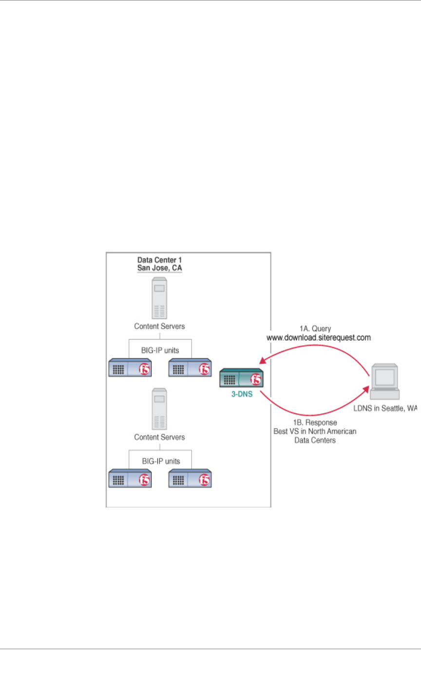
In Figure 7.1, a local DNS server in Seattle, Washington, sends a query for
the domain www.download.siterequest.com (1A). Based on the location
information in the query packet header, the 3-DNS Controller in the content
provider’s North American data center resolves the query to the best virtual
server in that data center, and sends an A record response to the Seattle
LDNS (1B).
Figure 7.1 DNS query resolution based on Topology load balancing mode
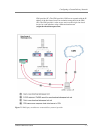
In Figure 7.2, a local DNS server in London sends a query for the same
domain, www.download.siterequest.com (2A). Based on the location
information in the query packet header, the 3-DNS Controller in the content
provider’s North American data center responds to the London LDNS with
delegation information (a CNAME record) about the DNS for the content
delivery peer (2B). The London LDNS then sends the redirected query
(based on the CNAME record) for www.download.siterequest.com to the


