


Back to Contents Page
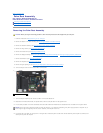
System Board Assembly
Dell™Latitude™E6400andE6400ATGand
MobileWorkstationPrecision™M2400ServiceManual
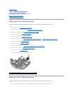
Removing the System Board Assembly
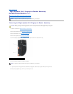
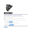
Replacing the System Board Assembly
The system board's BIOS chip contains the Service Tag, which is also visible on a barcode label on the bottom of the computer. The replacement kit for the
system board includes media that provides a utility for transferring the Service Tag to the replacement system board.
Removing the System Board Assembly
1. Follow the instructions in Before Working on Your Computer.
2. Remove the bottom of the base assembly (see Removing the Bottom of the Base Assembly).
3. Remove the card in the WWAN/FCM card slot, if present (see Removing a WWAN Card or Removing an FCM from the WWAN/FCM Slot).
4. Remove the card from the WLAN/WiMax card slot, if present (see Removing the WLAN/WiMax Card).
5. Remove the hinge covers (see Removing the Hinge Covers).
6. Remove the card from the WPAN/UWB/FCM card slot, if present (see Removing a WPAN (UWB/BT) Card or Removing an FCM from the WPAN/UWB/FCM
Slot).
7. Remove the memory modules (see Removing a Memory Module).
8. Remove the heatsink assembly (see Removing the Processor Heatsink Assembly).
9. Remove the processor (see Removing the Processor Module).
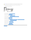
10. Disconnect the coin-cell battery cable from the system board.
11. Remove the hard drive (see Removing the Hard Drive).
12. Remove the modular drive (see Removing the Modular Drive).
13. Remove the display assembly (see Removing the Display Assembly (E6400 and M2400) or Removing the Display Assembly (E6400 ATG)).
14. Remove the LED cover (see Removing the LED Cover).
15. Remove the keyboard (see Removing the Keyboard).
16. Remove the right speaker grill (see Removing the Right Speaker Grill/Fingerprint Reader Assembly).
17. Remove the palm rest assembly (see Removing the Palm Rest Assembly).
18. Remove the card cage (see Removing the Card Cage).
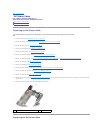
19. Disconnect the smart card cable from the system board.
20. Disconnect the 1394 daughtercard cable from the system board, and unroute the cable from the system board.
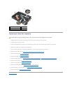
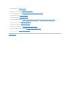
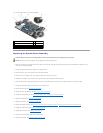
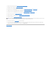
21. Remove three M2.5 x 5-mm screws labeled with white arrows from the system board.
22. Pull out on the top-left corner of the base assembly to release the connectors, while lifting the top-left corner of the system board.
23. Lift the top-right corner of the system board to disconnect the system board from the I/O card.
24. Disconnect the DC cable, which is connected to the bottom of the system board.
CAUTION: Before you begin the following procedure, follow the safety instructions that shipped with your computer.