


52 Installing System Components
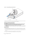
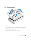
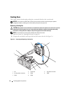
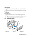
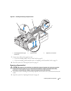
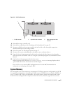
Replacing a Power Supply
1
Holding the lever in the open position, slide the new power supply into the chassis until the lever
contacts the system chassis. See Figure 3-6.
2
Close the release lever until the power supply is fully seated and the lever snaps into place behind the
lever release latch. See Figure 3-6.
NOTE: If you unlatched the cable management arm in step 2 of the previous procedure, relatch it. For
information about the cable management arm, see the system’s Rack Installation Guide.
3
Connect the power cable to the power supply and plug the cable into a power outlet.
NOTICE: When connecting the power cable, insert the cable through the strain-relief loop.
NOTE: After installing a new power supply in a system with two power supplies, allow several seconds for the
system to recognize the power supply and determine its status. The power-supply status indicator turns green to
signify that the power supply is functioning properly (see Figure 1-4).
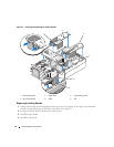
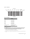
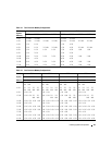
Expansion Cards
Expansion Card Installation Guidelines
Your system supports up to eight PCI-Express (PCIe) expansion cards installed in connectors on the
system board (see Figure 3-7 and Table 3-1):
• Slots 1 and 2 are x4 lane-width PCIe expansion slots. Slot 2 accommodates a full-length card.
• Slots 3 and 4 are x8 lane-width PCIe expansion slots. Both slots accommodate full-length cards.
• Slots 5 through 7 are x4 lane-width PCIe expansion slots. Slot 5 accommodates a full-length card.
• One expansion slot, labeled INTERNAL_STORAGE, is reserved for the system’s SAS controller card.
• If you are installing a Remote Access Control (RAC) card, it must be installed in the special card slot
marked RAC_CONN. See "RAC Card" on page 56