


Installing System Components 87
Installing the Chassis Intrusion Switch
CAUTION: Only trained service technicians are authorized to remove the system cover and access any of the
components inside the system. See your Product Information Guide for complete information about safety
precautions, working inside the computer, and protecting against electrostatic discharge.
1
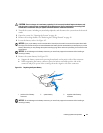
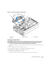
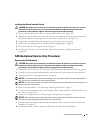
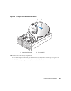
Connect the intrusion-switch cable to its system board connector. See Figure 3-25.
2
Align the two grooved sides of the top of the intrusion switch with the inside of the intrusion-switch
clip and then gently, but firmly, press in the switch until it is fully seated. See Figure 3-25.
3
If applicable, reinstall the heat sink onto processor 4. See "Processors" on page 62.
4
Replace the top cooling shroud. See "Replacing the Cooling Shrouds" on page 50.
5
Close the system. See "Closing the System" on page 47.
6
Reconnect the system to its electrical outlet and turn the system on, including any attached
peripherals.
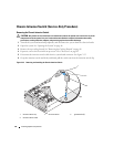
SAS Backplane (Service-Only Procedure)
Removing the SAS Backplane
CAUTION: Only trained service technicians are authorized to remove the system cover and access any of the
components inside the system. See your Product Information Guide for complete information about safety
precautions, working inside the computer, and protecting against electrostatic discharge.
1
If applicable, remove the bezel. See "Removing and Replacing the Optional Front Bezel" on page 45.
2
Turn off the system and attached peripherals, and disconnect the system from the electrical outlet.
3
Open the system. See "Opening the System" on page 46.
NOTICE: To prevent damage to the drives and backplane, you must remove the SAS drives and diskette/optical
drive carrier from the system before removing the backplane.
NOTICE: You must note the number of each hard drive and temporarily label them before removal so that you can
replace them in the same locations.
4
Remove all SAS hard drives. See "Removing a Hot-Plug Hard Drive" on page 73.
5
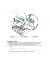
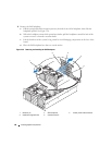
To remove the optical/diskette drive carrier, pull the release latch forward, then slide the carrier out of
the chassis. See Figure 3-18.
6
Remove the cooling shrouds. See "Removing the Cooling Shrouds" on page 49.
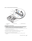
NOTICE: When disconnecting the control-panel cable, hold the white pull-tab next to the control-panel cable
connector to prevent damage to the SAS backplane or the cable itself.
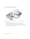
7
Disconnect the control-panel cable from the control-panel cable connector on the front of the SAS
backplane. See Figure 6-3.
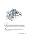
8
Disconnect the SAS, interface, and power cables from the back of the SAS backplane.