


80 Installing System Components
6
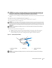
Install the new system battery.
a
Support the battery connector by pressing down firmly on the positive side of the connector.
b
Hold the battery with the "+" facing up, and slide it under the securing tabs at the positive side of
the connector.
c
Press the battery straight down into the connector until it snaps into place.
7
Replace the cooling shrouds. See "Replacing the Cooling Shrouds" on page 50.
8
Close the system. See "Closing the System" on page 47.
9
Reconnect the system to its electrical outlet and turn the system on, including any attached peripherals.
10
Enter the System Setup program to confirm that the battery is operating properly. See "Using the
System Setup Program" on page 31.
11
Enter the correct time and date in the System Setup program's
Time
and
Date
fields.
12
Exit the System Setup program.
13
To test the newly installed battery, turn off the system and disconnect it from the electrical outlet for
at least an hour.
14
After an hour, reconnect the system to its electrical outlet and turn it on.
15
Enter the System Setup program and if the time and date are still incorrect, see "Getting Help" on
page 129 for instructions on obtaining technical assistance.
Control Panel Assembly (Service-Only Procedure)
Removing the Control Panel
CAUTION: Only trained service technicians are authorized to remove the system cover and access any of the
components inside the system. See your Product Information Guide for complete information about safety
precautions, working inside the computer, and protecting against electrostatic discharge.
1
Turn off the system and attached peripherals, and disconnect the system from the electrical outlet.
2
Open the system. See "Opening the System" on page 46.
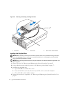
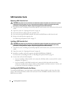
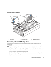
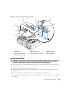
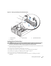
3 Disconnect the control panel data cable from the control panel board.
See Figure 3-22.
4 Disconnect the display module cable from the control panel board.
See Figure 3-22.
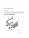
5
Remove the three Torx screws securing the control panel board to the system chassis and remove the
board.
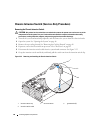
6
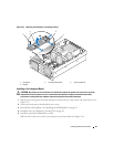
Remove the display module:
a
Insert the end of a paper clip into the hole on the right side of the display module and gently pry
the label off.
b
Remove the two Torx screws that secure the display module to the system chassis.
7
Remove the display module from the chassis cutout.