Dialogic
®
PBX Integration Board User’s Guide
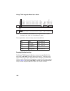
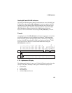
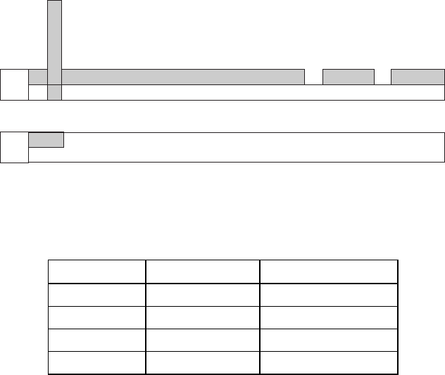
Line Key 1
00 0F 00 00 00 00 00 00 00 00 00 00 00 00 00 00 xx 00 00 00 xx 00 00 00
00 01 02 03 04 05 06 07 08 09 10 11 12 13 14 15 16 17 18 19 20 21 22 23
00 00 xx xx xx xx xx xx xx xx xx xx xx xx xx xx xx xx xx xx xx xx xx xx
24 25 26 27 28 29 30 31 32 33 34 35 36 37 38 39 40 41 42 43 44 45 46 47
Line Key 2
Line Key 3
Line Key 4
Line Key 5
Line Key 6
Line Key 7
Line Key 8
Line Key 9
Line Key 10
Line Key 11
Line Key 12
Line Key 13
Line Key 14
Line Key 15
Line Key 16
Not Used
MWI
CNF Key
FCN Key
Not Used
LNR/SPD Key
ANS Key
SPKR Key
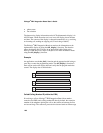
Data
Byte
Data
Byte
ICM
MIC
NOTE: Bit 3 determines if the indicator is red or green. If bit 3 is 0, the
indicator is red; if bit 3 is 1, the indicator is green.
The example below shows the binary data for On and Wink.
Bit Hex 7 6 5 4 3 2 1 0
On 0x7 (red) 0 1 1 1 x x x x
On 0xF (green) 1 1 1 1 x x x x
Wink 0x2 (red) 0 0 1 0 x x x x
Wink 0xA (green) 1 0 1 0 x x x x
Pressing Flexible Line Keys
The Dialogic
®
PBX Integration Board can “press” any of its Flexible Line
keys using the dx_dial( ) function. Refer to the Dialogic
®
PBX Integration
Software Reference for more information about dialing keys. Each Flexible
Line key on the DTerm Series III telephone is assigned a dial string sequence
(refer to
Table 36). By using the dx_dial( ) function and the appropriate dial
string, the PBX Integration Board can press any Flexible Line key.
156


