Dialogic
®
PBX Integration Board User’s Guide
value of eight [0x08] indicates ON), while the green light has six possible
values. The status of the indicators is obtained by bitwise-ANDing the
returned value from the green light with the value from the red light (green
light value + red light value). In other words, the value for a line indicator in
use with a call (after ANDing with 0x0f, all the values shown below in the
least significant byte value) would be nine--0x08 (for red light on) + 0x01 (for
green light on). The status conditions for each byte (least significant) of the
green light are defined as indicated in
Table 2.
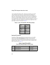
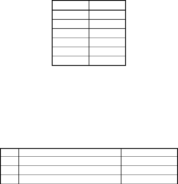
Table 2. Avaya 7434 and 8434 LED Indicator States
State Value (Hex)
off
0x00
on
0x01
ringing
0x02
hold
0x03
error
0x04
unknown
0x05
Reading LED Indicators
The Dialogic
®
PBX Integration Board can determine the state of its LED
indicators by using the d42_indicators( ) function to retrieve the LED
indicators data. This function places the Line Indicator data (34 bytes) in an
application buffer. Bytes 1-34 contain the indicator status for Memory Keys
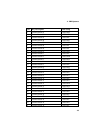
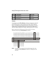
00-33, respectively (see
Table 3).
Table 3. Avaya 7434 and 8434
Direct Key Dialing Strings for Feature Keys
Byte Key Description Dial String
1 Feature Button 00 <ESC>KA
2 Feature Button 01 <ESC>KB
3 Feature Button 02 <ESC>KC
42


