Dialogic
®
PBX Integration Board User’s Guide
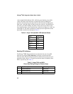
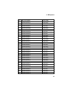
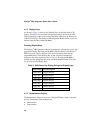
Byte Key Description Dial String
32 Feature Button 31 <ESC>Kf
33 Feature Button 32 <ESC>Kg
34 Feature Button 33 <ESC>Kh
Example
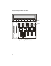
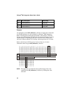
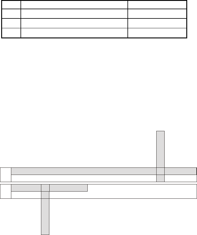
An application uses the d42_indicators( ) function to retrieve the current data
for the LED indicators on a given channel on a Dialogic
®
PBX Integration
Board. The data placed in the application buffer is shown below. If the data
for byte 19 is 0x09 and byte 28 is 0x03, the red and green indicators are on for
Feature Button 19, indicating that the line is in use for a call, and the green
indicator for Memory Button 28 is flashing, indicating that the call is on hold.
Refer to the Dialogic
®
PBX Integration Software Reference for more
information about using the d42_indicators( ) function.
24 25 26 27 28 29 30 31 32 33 34 35 36 37 38 39 40 41 42 43 44 45 46 47
16 17 18 19 20 21 22 23
Data
Data
Byte
Byte
00 00 00 00 00 00 00 00 00 00
00 01 02 03 04 05 06 07 08 09 10 11 12 13 14 15
Feature Button 00
Button 01
Button 02
Button 03
Button 04
Button 05
Button 06
Button 07
Button 08
Button 09
Feature
Feature
Feature
Feature
Feature
Feature
Feature
Feature
Feature
Feature
Feature
Feature
Feature
Feature
Feature
Feature
Feature
Feature
Feature
Button 24
Button 25
Button 26
Button 27
Button 28
Button 29
Button 30
Button 31
Button 32
Button 33
Feature
Feature
Feature
Feature
Feature
Feature
Feature
Feature
Feature
Feature
Feature
Feature
Feature
Feature
Button 10
Button 11
Button 12
Button 13
Button 14
Button 15
Button 16
Button 17
Button 18
Button 19
Button 20
Button 21
Button 22
Button 23
00 00 00 00 00 00 00 00 00 09 00 00 00 00
00 00 00 00 03 00 00 00 00 00 xx xx xx xx xx xx xx xxxx xx xx xx xx xx
NOTE: The application can obtain the least significant byte of the value
returned by the d42_indicators( ) function by ANDing that value
with 0x0f.
44


