


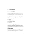
3. PBX Integration Overview
PCI9052
Interface
Front End
To
PBX
100 MHz Onyx
DSP with 256K x
24 SRAM with
2 Wait States
CT812 Time
Slot
Interchange
H.100
Bus
Address Bus
Data Bus
Glue Logic
FPGA
PCI Bus
Interface
Control
Lines
TDM
Signals
Configuration Data
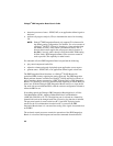
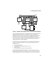
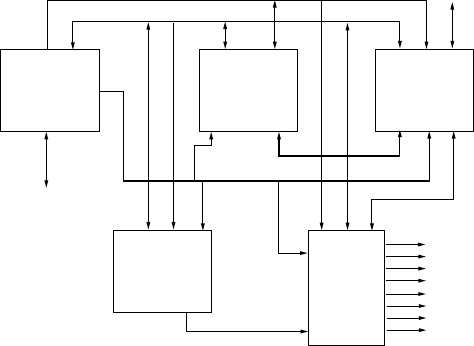
Figure 1. Dialogic
®
PBX Integration Board Functional Block Diagram
Voice files stored on the host PC are read by the host driver and transferred to the
Dialogic
®
PBX Integration Board via the PCI Bus. These voice signals are
buffered by the control processor and decoded into 64 Kbps PCM signals by the
DSP. These PCM voice signals are then sent to the PBX interface link for
transport to the caller. A system-wide, TDM signal sharing bus, called CT Bus, is
also provided for the exchange of signal streams with other resource boards,
signal transport boards, or other interfaces.
In addition to having all the standard features of a Dialogic
®
D/41D Board, the
Dialogic
®
PBX Integration Board can access enhanced PBX features, when
available, such as:
• call transfer/conference
• turn phone message waiting indicators on or off
• callback request
• calling number identification (Calling Number ID).
The Dialogic
®
PBX Integration Board has an on-board microprocessor and a
high-speed Digital Signal Processor (DSP) to provide voice and call processing.
Dialogic
®
Springware voice processing firmware is downloaded from the host
33