Installation 23
Emerson Energy Systems Rectifier 200I/48NT5C05C Installation and User Manual
3.5. Connecting the dc output terminals to the busbars
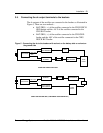
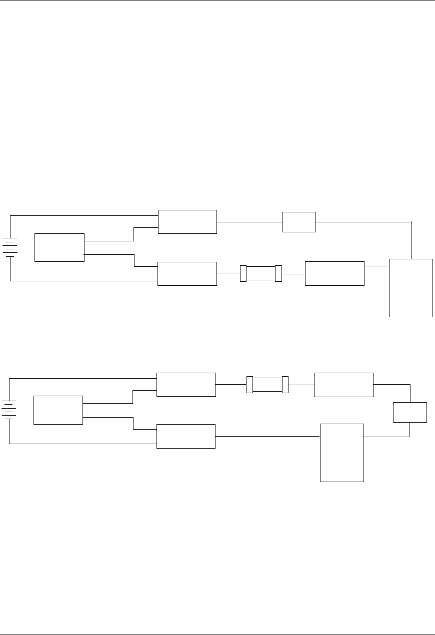
The dc outputs of the rectifier are connected to the busbars as illustrated in
Figure 5. There are two methods :
• BAT GRD ( + ) of the rectifier connected to the CHG/ DISCH
GRD busbar and the –48 V of the rectifier connected to the
CHG BAT busbar
• BAT GRD ( + ) of the rectifier connected to the CHG GRD
busbar and the -48V of the rectifier connected to the CHG/
DISCH BAT busbar
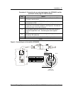
Figure 5 - Connecting the dc to the busbars with a shunt on the battery side or a shunt on
the ground side
RECTIFIER
+
-
BAT GRD
-48V
CHG / DISCH
GRD BUSBAR
CHG BAT
BUSBAR
SHUNT
DISCHARGE
BAT BUSBAR
FUSE
PANEL
+
-
LOAD
SHUNT ON THE BATTERY SIDE
RECTIFIER
+
-
BAT GRD
-48V
CHG GRD
BUSBAR
CHG / DISCH
BAT BUSBAR
SHUNT
DISCHARGE
GRD BUSBAR
+
-
LOAD
FUSE
PANEL
SHUNT ON THE GRD SIDE ( PREFERRED CONFIGUR
A
TION )


