


26 Installation
UM5C05C P0745680 Standard 6.00 October 2001 Emerson Energy Systems
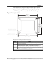
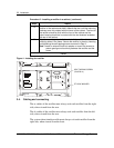
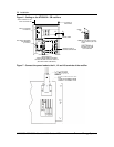
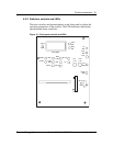
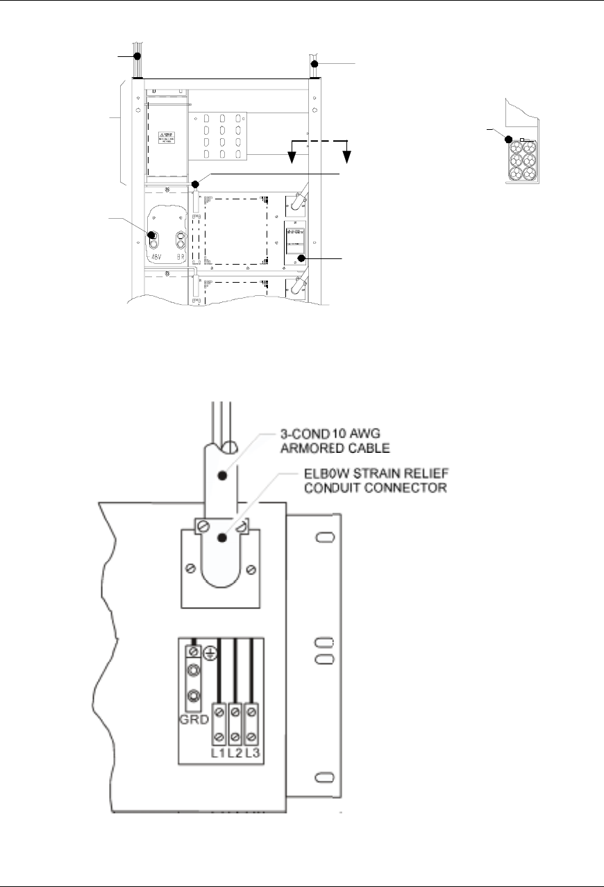
Figure 6 - Cabling ac the NT5C05CA / CB rectifiers
PART OF OPTIONAL
KIT P0872151
HEX HEAD CAP SCREW
AND WASHERS
( 4 PLACES )
SIGN
A
L
C
A
BLEST
O
THE
PLANT CONTROLLER
REMOVE PLATE TO
ACCESS CONNECTORS
AC FEED TO
RECTIFIERS
AA
REAR VIEW OFA
TOP FEDARRANGEMENT SHOWING
OPTIONAL BUSBAR COVER KIT P0872151
( WITH REARPANELS REMOVED )
SECTION A-A
SHOWING TOP VIEW
OF AC CABLING
Note: Dress the cables carefullyto
clear the insertion path of th
e
rectifier.
CABLE
TIE
SIGNAL CABLE
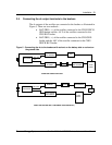
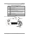
Figure 7 - Connect the power leads to the L1, L2 and L3 terminals of the rectifier