


8 Contents
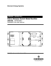
UM5C05C P0745680 Standard 6.00 October 2001 Emerson Energy Systems
6. Maintenance................................................................................................. 49
6.1. Replacing the air filter ................................................................................ 49
6.2. Replacing the fan unit ................................................................................ 49
6.3. Calibrating the Volt / Amp Multimeter......................................................... 50
6.4. Resetting the rectifier after an HVSD ( high voltage shutdown )................ 51
7. Troubleshooting .......................................................................................... 53
8. Appendix A : Replacement parts ............................................................... 55
9. Appendix B : Technical service assistance.............................................. 57
9.1. Local toll-free prefixes................................................................................ 57
9.2. Toll-free technical assistance numbers...................................................... 58
10. Abbreviations and acronyms ..................................................................... 59
List of Figures
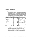
Figure 1 - Front view of the modular 200I / 48 switch mode rectifier ................... 11
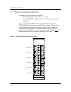
Figure 2 - Typical mounting in a cabinet or frame................................................ 12
Figure 3 - Anchoring the cabinet.......................................................................... 21
Figure 4 - Installing the rectifier............................................................................ 22
Figure 5 - Connecting the dc to the busbars with a shunt on the battery
side or a shunt on the ground side ...................................................... 23
Figure 6 - Cabling ac the NT5C05CA / CB rectifiers............................................ 26
Figure 7 - Connect the power leads to the L1, L2 and L3 terminals of the
rectifier ................................................................................................. 26
Figure 8 - Connecting ac to the rectifier NT5C05CC ........................................... 27
Figure 9 - Typical connections between rectifiers and the conventional
controller .............................................................................................. 28
Figure 10 - Front panel controls and LEDs .......................................................... 33
Figure 11 - Replacing the fan unit........................................................................ 49
List of Tables
Table 1 - Mechanical specifications of the rectifier .............................................. 13
Table 2 - Electrical specifications of the rectifier.................................................. 13
Table 3 - Operation specifications of the rectifier ................................................ 14
Table 4 - Ambient conditions for the rectifier ....................................................... 15
Table 5 - Mechanical specifications of the NT6C43CB 1200 A cabinet .............. 16
Table 6 - Electrical specifications of the NT6C43CB........................................... 16
Table 7 - Ambient conditions for the NT6C43CB 1200 A cabinet........................ 16
Table 8 - Pin assignment for connectors J7 to J12.............................................. 29
Table 9 - Pin assignment for connector J13 ........................................................ 30
Table 10 - Designation of the LEDs on the front panel........................................ 34
Table 11 - Adjusting the potentiometers and switches ........................................ 36
Table 12 - Rectifier input / output signals to the controller................................... 36
Table 13 - Setting the start-up delay.................................................................... 41
Table 14 - Control signal connections on P1 ....................................................... 42
Table 15 - Standard settings for the rectifier........................................................ 45
Table 16 - Diagnosing system faults.................................................................... 53
List of Procedures
Procedure 1 - Installing the rectifier in a frame .................................................... 20
Procedure 2 - Installing a rectifier in a cabinet..................................................... 21
Procedure 3 - Securing the dc output terminals to the busbars of the cabinet.... 24
Procedure 4 - Typical dc cabling in a frame application ...................................... 24
Procedure 5 - Cabling the ac input to the NT5C05CA / CB rectifiers .................. 25