


42 Functional description
UM5C05C P0745680 Standard 6.00 October 2001 Emerson Energy Systems
Remote ON / OFF control TR
When a ground signal is applied to the 'Temporary Release' ( TR ) input,
the rectifier inhibits its operation and triggers the RFA. When the remote
ground signal is discontinued the rectifier returns to normal operation ( see
Table 14 ).
Start up delay DIP switch
The rectifier can provide a start-up delay of from 4 seconds up to
120 seconds, with a resolution of 8 seconds and an accuracy of +
1 second.
Use of this feature is recommended when two or more rectifiers are
connected to a common ac input to stagger the inrush currents. A front
panel DIP switch can be set to provide the start-up delays listed in Table
13.
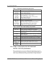
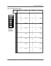
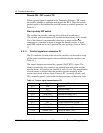
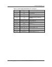
4.2.11. Control signals on connector P1
The P1 connector, located at the rear of the rectifier, can be used to verify
all the control and alarm signals when troubleshooting the rectifier ( see
Table 14 ).
The control inputs are activated by a ground ( BAT RTN ) signal. The
alarms, extended by relay contacts, are isolated from each other and the
rectifier frame. All contacts are rated 60 V and 0.5 A dc. The normal status
of each contact is defined when the rectifier operates normally in the
remote sense mode with no alarm. Contacts NC ( normally closed ) and
NO ( normally opened ) refer to the de-energized state of their relay coils.
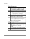
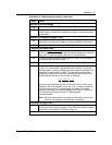
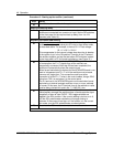
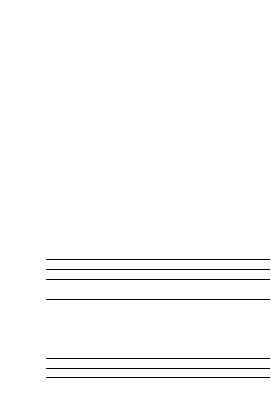
Table 14 - Control signal connections on P1
Connection Signal Description
P1-1 EQL Equalize
P1-2
RC − Remote sense ( − )
P1-3 HVSDR High voltage shutdown reset
P1-4 RFA ( NC ) Rectifier fail alarm ( NC )
P1-5 FAN ALM ( NC ) Fan fail alarm ( NC contact )
P1-6 FAN ALM ( C ) Fan fail alarm ( C )
P1-7
SH−
Output current shunt voltage ( - )
P1-8 RFA ( NO ) Rectifier fail alarm ( NO )
P1-9 SENSE ( C ) Sense fail alarm ( C )
P1-10 SENSE ( NO ) Sense fail alarm ( NO )
continued