


38 Functional description
UM5C05C P0745680 Standard 6.00 October 2001 Emerson Energy Systems
The rectifier can be started when it is connected across a completely
discharged battery without requiring human intervention or operating
protective devices. A transition from constant voltage operation to
constant current operation and from constant current operation to constant
voltage operation occurs automatically, as determined by the output
current. The current limiting circuit is functional in float and equalize
modes.
4.2.8. Rectifier parallel operation
The rectifier can operate in parallel with other rectifiers having similar
output characteristics. It shares the total load in proportion to its output
rating. Two methods for sharing load current are available :
• Slope sharing
• Forced sharing
Selecting either mode is done by setting the two bottom DIP switches,
SLS / FS, located on the front panel. The rectifier is factory set to the slope
sharing mode.
Slope sharing ( SLS )
When both bottom DIP switches are set to the SLS position, conventional
load sharing is achieved through a -300 mV slope on the output voltage of
the rectifier, from no load to full load. This mode should be used when
rectifiers from different manufacturers are not all equipped with the forced
load-sharing feature. In this mode, the units will share the load within
±10% of their maximum output rating.
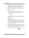
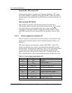
To accurately preset the float voltage of the rectifier, its current in the plant
environment must be predicted and the preset output floating voltage must
be calculated using the formula found below. In the formula, 0.8 volts is
added to the float voltage to compensate for an internal voltage drop when
the rectifier dc breaker is put in the ON position.
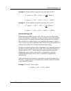
V ( preset ) = Vo ( desired ) + 0.8 V + ( Io ( running
) x 300 mV )
200