


Installation 29
Emerson Energy Systems Rectifier 200I/48NT5C05C Installation and User Manual
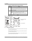
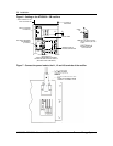
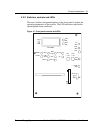
Procedure 8 - Connecting an NT5C05CC rectifier directly to a controller
Step Action
1
If an NT6C43PB interconnect board is not available, each rectifier
must be connected directly to the controller with the following
cables :
• P0723784, P0723785 or P0723786 ( for conventional
controllers )
• P0723708, P0723709 or P0723210 ( for front access
controllers )
end
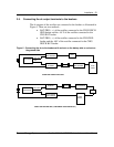
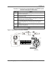
For controllers not manufactured by Emerson Energy Systems see Table
12 in the " Functional Description " chapter describing the pin assignments
of the rectifier. Refer to Table 8 for the pin assignments of connectors J7
to J12 on board NT6C43PB.
Note: The alarm and control signals in Table 8 are all ground
signals except for the RC– signal that is a –48 V
battery signal.
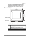
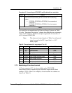
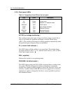
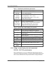
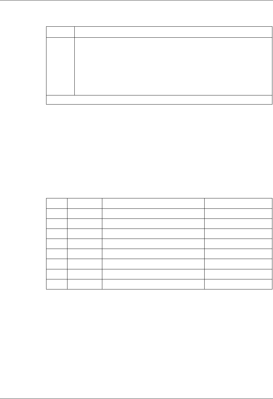
Table 8 - Pin assignment for connectors J7 to J12
Pin Label Function Input/ Output
1
EQL Equalize Input
2
RG+ Remote sense Input
3
RC– Remote sense Input
4
FAN ALM Fan fail alarm Output
5
HVSDR High voltage shutdown reset Input
6
HVSD High voltage shutdown Input
7
RFA Rectifier failure alarm Output
8
TR Temporary release Input
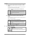
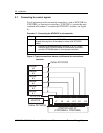
3.7.1. Monitoring of the shunt current
A 12-pin connector ( J13 ) is also available on the NT6C43PB
interconnect board for monitoring the individual output current shunt
readings ( 250 A / 50 mV for example ) of each rectifier in a cabinet or a
frame ( see Table 9 ).