


7
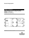
Emerson Energy Systems Rectifier 200I/48NT5C05C Installation and User Manual
Contents
1. General information .................................................................................... 11
1.1. Purpose of this manual .............................................................................. 11
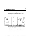
1.2. Models and mounting configurations ......................................................... 12
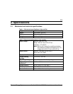
2. Specifications .............................................................................................. 13
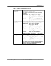
2.1. Mechanical and electrical specifications .................................................... 13
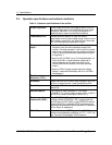
2.2. Operation specifications and ambient conditions....................................... 14
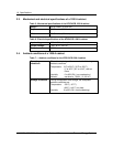
2.3. Mechanical and electrical specifications of a 1200 A cabinet .................... 16
2.4. Ambient conditions of a 1200 A cabinet..................................................... 16
3. Installation.................................................................................................... 17
3.1. Mounting configurations............................................................................. 17
3.2. Tools and test equipment........................................................................... 17
3.3. Cautions and Warnings.............................................................................. 17
3.3.1. Installing in a frame.............................................................................. 20
3.3.2. Installing in a cabinet ........................................................................... 20
3.4. Cabling and connecting.............................................................................. 22
3.5. Connecting the dc output terminals to the busbars.................................... 23
3.5.1. Securing the dc output terminals to the busbars in a 1200 A cabinet . 24
3.5.2. Running and connecting the dc between busbars and a rectifier........ 24
3.6. Connecting ac to the rectifiers.................................................................... 24
3.7. Connecting the control signals ................................................................... 28
3.7.1. Monitoring of the shunt current ............................................................ 29
4. Functional description................................................................................ 31
4.1. Overview .................................................................................................... 31
4.1.1. Input circuit .......................................................................................... 31
4.1.2. Output circuit........................................................................................ 31
4.1.3. Monitoring and control circuits............................................................. 32
4.1.4. Output capacitors................................................................................. 32
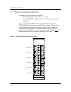
4.2. Description of the front panel ..................................................................... 32
4.2.1. Breakers .............................................................................................. 32
4.2.2. Switches, controls and LEDs............................................................... 33
4.2.3. Front panel LEDs................................................................................. 34
4.2.4. Local and remote adjustments and controls........................................ 35
4.2.5. Voltage / current displaytest and measurement............................... 36
4.2.6. Float and equalize voltage control ....................................................... 37
4.2.7. Current limit adjustment and rectifier regulating test ........................... 37
4.2.8. Rectifier parallel operation ................................................................... 38
4.2.9. HVSD ( high voltage shutdown ).......................................................... 40
4.2.10. TR ( temporary inhibition ) and sequential start................................... 40
4.2.11. Control signals on connector P1.......................................................... 42
5. Operation...................................................................................................... 45
5.1. Standard settings ....................................................................................... 45
5.2. Starting up and adjusting ........................................................................... 46