


24 Installation
UM5C05C P0745680 Standard 6.00 October 2001 Emerson Energy Systems
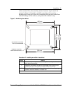
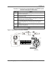
3.5.1. Securing the dc output terminals to the busbars in a 1200 A
cabinet
For cabinet applications, no dc cabling is required; the output terminals of
the rectifier are connected directly to the busbars.
Procedure 3 - Securing the dc output terminals to the busbars of the
cabinet
Step Action
1
Connect the BAT GRD output terminal of the rectifier to the BR
busbar, and the –48 V output terminal of the rectifier to the –48 V
busbar located at the rear of the cabinet.
2
Tighten the bolts by applying a torque of 6.5 ± 0.5 ft-lbs ( 8.5 ±
0.5 N-m ).
end
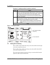
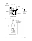
3.5.2. Running and connecting the dc between busbars and a
rectifier
For frame applications, use terminal lug A0361762, supplied with the unit,
and no. 110 ( 4/0 ) metric cable.
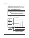
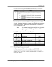
Procedure 4 - Typical dc cabling in a frame application
Step Action
1
Connect the BAT GRD output terminal of the rectifier to the CHG
GRD busbar of the power plant. Connect the –48 V output terminal
of the rectifier to the CHG / DISCH BAT busbar of the power plant
( see Figure 5 ).
2
Apply a torque of 6.5 ± 0.5 ft-lbs ( 8.5 ± 0.5 N-m ) on the bolts
securing the lugs to the rectifier terminals.
end
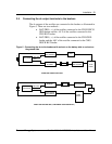
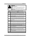
3.6. Connecting ac to the rectifiers
WARNING
Electrical connections should meet standards
The electrical installation must be carried out by qualified
personnel and in accordance with local electrical codes.